25
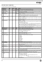
Backlight maximum brightness “Max LED Lux (%)” (33).
This is the
luminous intensity, expressed as a percentage, of the backlighting LEDs
of the panel keypad and LCD screen when the panel is on. The entrance
panel reaches the maximum brightness value when performing functions
and returns to the minimum value after approx. 10 seconds of inactivity.
Camera LED brightness “TLC Lux (%)” (34).
This is the luminous inten-
sity, expressed as a percentage, of the camera lighting LEDs. (Only for
entrance panels connected to cameras).
Seconds, Minutes, Hours, Day of the month, Month, Year, Day of the
week. (35) – (41).
These parameters configure the entrance panel clock
– calendar.
External volume (42) Internal volume (43) Balance (44).
The entrance
panel is equipped with digital trimmers for adjusting the audio volume and
balance. These parameters directly control the trimmers and can be modi-
fied by directly typing the new parameter value or by adjusting the volume
while making a call.
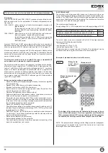
F1 Code (45).
This parameter is for programming the code to activate fun-
ction F1 from keypad. To enter the code simultaneously press buttons
R
+
2
ABC
.
F2 Code (46).
This parameter is for programming the code to activate fun-
ction F2 from keypad. To enter the code simultaneously press buttons
R
+
3
DEF
.
First number in memory “1 Num. Memory” (47).
This parameter is for programming the quick call number associated with
the “
” button. If the number is 0, the function is disabled.
Second number in memory “2 Num. Memory” (48).
This parameter is for programming the quick call number associated with
the “
” button. If the number is 0, the function is disabled.
The quick call function is secondary to the switchboard call function. If pa-
rameter 19 “Enab. Switchbd Call” is enabled, when “
” is pressed, the call
to switchboard is sent on the digibus channel to the main entrance panel /
switchboard.
External reader address “Ext 1 – 8 Address” (49) – (56).
Up to 8 tran-
sponder readers can be connected to the entrance panel via the interphone
cable riser digibus channel, terminal 1. The ID code of the readers from
which the entrance panel can receive the key must be programmed in these
parameters.
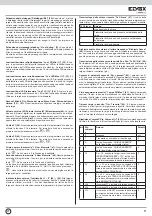
Transmission of received key “Tx Key” (57).
The keycode received by
one of the transponder readers connected to the interphone cable riser digi-
bus channel, can be forwarded by the entrance panel in the following ways:
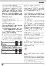
Access to hidden parameters “Hidden paras” (60).
parameters from 61
to 67 are not normally accessible. These parameters must only be modified
on the recommendation of Elvox technicians to prevent malfunctions or da-
mage to the entrance panel. To access the hidden parameters, type “27” in
Hidden Paras. Access to the parameters is automatically deactivated when
returning to the normally accessible parameters.
Monitor power-off cycle “Mon. Off Time” (61).
This parameter expresses
the activation time, in tens of milliseconds, of the +I output. The entrance
panel +I terminal is connected to the +I terminal present on power supply
units type 6941 and 6948 and checks the power supply of the monitors to
the + - terminals.
Entrance panel in transit timeout “Transit Time” (62).
This is the ma-
ximum time, in minutes, for which the entrance panel remains in transit.
To prevent system malfunctions from blocking the entrance panel in the
engaged status, when this time has elapsed the entrance panel interrupts
the communication and also frees the interphone cable riser to which it is
connected.
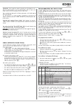
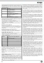
Command repetition “Command Rep. (+)” (63).
This command enables
the forwarding or repetition of certain special commands, as shown in the
table below: (default bit 2+7+8)
Tx Key
=
Action:
0
Doesn’t transmit the key
1
Transmits the key if it is present in the entrance panel data-
base
2
Transmits the key is it is not present in the entrance panel
database
3
Always transmits the key
Request confirmation code from transponder reader “Request Passw”
(58).
When the entrance panel receives a key it can request a confirmation
from the transponder reader sending a message encoded with a password.
If this parameter is equal to 1 then confirmation is requested, otherwise not.
Transmission of key to Up or Down serial line “Tx UP / Down” (59).
If parameter 57 is different from 0, this parameter decides which channel the
keycode will be forwarded on: if para. 59 = 0 the entrance panel transmits
the key on the interphone cable riser digibus channel (UP) otherwise on the
digibus channel to the main entrance panel / switchboard (down).
bit
Command
rep. =
Action:
Default
0
None
xxx
0
1
Transmits a double reset command
0
2
4
Forwards the “NO KEY” command over the
interphone cable riser digibus line
1
3
8
Forwards the “NO KEY” command over the
main entrance panel digibus line
0
4
16
If = 16, when the entrance panel receives the
IN TLC command it forwards the
command without modifying it, otherwise it
only forwards intercom without camera.
0
5
32
If = 32: if the entrance panel receives an “S”
command from the serial line on the INTER-
PHONE CABLE RISER side addressed to
another device, it forwards it over the MAIN
ENTRANCE PANEL serial line.
0
6
64
If = 64: if the entrance panel receives an “S”
command from the serial line on the MAIN
ENTRANCE PANEL side addressed to
another device, it forwards it over the INTER-
PHONE CABLE RISER serial line.
0
7
128
Forwards the F1 command on the main panel
serial line.
1
8
256
Forwards the F2 command on the main panel
serial line.
1
9
512
The RESET command from the main en-
trance panel is forwarded to the interphone
cable riser even if the initial user - final user
window is closed.
0
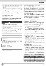
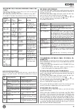
Activate datalogger “Datalogger (R9)” (30).
If set to 1 the entrance panel
datalogger is activated. The datalogger records messages generated by
the entrance panel or which are transmitted over the databuses connected
to the entrance panel (cable riser serial line and serial line to the main
entrance panel) and can be displayed by simultaneously pressing buttons
R + 9. For each message the entrance panel stores the ID of the recipient,
the type of command, the time it was detected, the direction of transit and
the total number of stored messages. The entrance panel stores in memory
the last 400 messages detected. The events are erased if the power to the
entrance panel is interrupted.The datalogger is a useful tool for testing a
system and identifying possible faults.
Activate debug messages “Disp. debug ” (31).
If set to 1 every command
addressed to the entrance panel is shown on the display, indicating the type
of command and the sender ID.
This is a useful tool for testing a system and identifying possible faults.
Backlight minimum brightness “Min LED Lux (%)” (32).
This is the luminous intensity, expressed as a percentage, of the backli-
ghting LEDs of the panel keypad and LCD screen when the panel is in
standby. The entrance panel reaches the minimum brightness value after
approximately 10 seconds of inactivity since the last completed action.
EN

