background image

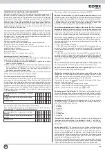
27

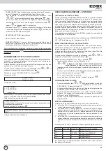
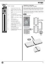
Push-but-
ton

Num.HW

Num.SW

Action if button pressed

P1 

1

0

Call user 1

P2 

2

88000001  Call user 88000001

P3 

Call user 4

P4 

4

Call user 4

HARDWARE – SOFTWARE ASSOCIATION

(Only for version 1282/P and 1286/P)

Each push-button of the entrance panel is associated with a hardware num-
ber (generated by the circuit board) from 1 to 31 (maximum number of 
push-buttons that can be connected to the entrance panel). If the entrance 
panel is required to serve users with a higher numbering range, for exam-
ple from 1000 to 1020, or to call a particular user from a push-button, e.g. 
calling the switchboard from the main entrance panel by pressing the first 
push-button, or calling the same internal user from two push-buttons etc; 
each hardware code can be associated with a software number which the 
entrance panel will use to send the call.
Push-button HW-SW associations can only be programmed if parameter 
07 is different from 0.

To program the associations use the “HW - SW ASSOCIATION” menu on 
the entrance panel, or programmer 950B.

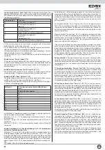
ENTRANCE PANEL HW – SW ASSOCIATION MENU

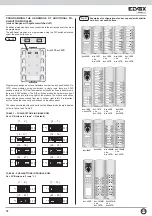
To access the “HW - SW ASSOCIATION” menu, simultaneously press pu-
sh-buttons R + 4 and enter the technical programming password (parameter 
8). The default value is 123.
The entrance panel initially displays the firmware version then after 10 se-
conds or when a button is pressed it enters the setup menu.

The various submenu items can be scrolled using the “

” and “

” but-

tons. The selectable submenu is indicated by the “

” arrow.

Select the item “HW - SW ASSOC.” and press “

”.

‡ 6FUROOWKHOLVWRIDVVRFLDWLRQVXVLQJWKH³

” and “

” buttons. 

The en-

trance panel does not display the codes of all push-buttons but only 
the first 6. 

The list of displayed push-buttons is lengthened each time by 

6 additional elements behind the last programmed element. 

‡ )LQGWKHKDUGZDUHQXPEHURIWKHSXVKEXWWRQWKDW\RXZDQWWRSURJUDP

enter the associated software code and press “

”.

‡ ,I\RXZLVKWRGHOHWHDQGDVVRFLDWLRQDIWHULGHQWLI\LQJKHSXVKEXWWRQ

enter the code 0 and press “

”.

PROGRAMMING WITH 950B

‡ 6FUROOWKHPHQXVXVLQJWKH³

” and “

” buttons on the programmer 

until the “ASSOC. BUTTONS” menu is selected and press the OK button.

‡ 7KHHQWUDQFHSDQHOHPLWVDFRQILUPDWLRQWRQHDQGWKHPHVVDJH³35(66

BUTTON to CHANGE” appears on the programmer display

‡ 3UHVVWKHFDOOSXVKEXWWRQWRZKLFK\RXZDQWWRDVVRFLDWHWKHVRIWZDUH

number. The following message appears on the programmer display: 
SW. NUM=xxx” and below it “SW.N=yyyyyyyy”

‡ (QWHUWKHVRIWZDUHQXPEHUWKDW\RXZDQWWRDVVRFLDWHDQGSUHVVWKH2.

button on the programmer.

OPERATING MODES

The entrance panel has three operating modes linked to Par.07 (SW en-
coding):
A. If SW encoding = 0 the entrance panel activates all push-buttons, sen-

ding the call with the hardware number associated with the push-button;

B. If SW encoding = 1 the entrance panel only activates push-buttons which 

have an associated software number different from 0. For example if the 
software number of P1 is 0, the number of P2 is 5 and the number of 
P3 is 10, the entrance panel activates only P2 and P3 and sends calls 
with the associated software number, while nothing happens when P1 is 
pressed;

C. If SW encoding = 2 the entrance panel activates all push-buttons, sen-

ding the call with the software number if the associated software number 
is different from 0, sending the call with the hardware number if the as-
sociated software number parameter is equal to 0.

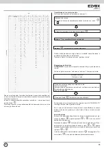
For example if Par.07 is equal to 2, programming is as follows:

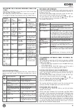
In this way it is only possible to modify the encoding of certain push-buttons, 
leaving the others unchanged.

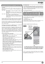
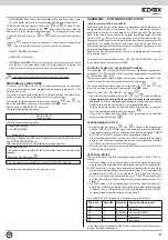
‡ 7,0(%$1'6(DFKNH\FDQEHDVVRFLDWHGZLWKWLPHEDQGVIURPDWRWDO

of 16 available, which can be programmed from the time band menu. 

To modify the time band select it using the “

 and 

” buttons. The se-

lected time band is indicated by the “

” arrow. Enter the new value, for 

values from 1 to 9 enter the digit preceded by “0” for example for time band 

5, enter 05 or 5 and press the “

” or “

” button to pass to the next time 

band. 

Pressing “

” passes to the next submenu. To save the new setting press 

”, then scroll all the submenus until the next key is reached.

‡ 6(/(&75($'(51RWXVHG

‡ 86(5'$7$1RWXVHG

‡ ,17(51$/180%(57KLVLVWKHQXPEHURIWKHLQWHUQDOXVHUDVVRFLDWHG

with the key. It is useful when, using the “data organizer” program, you 
want to trace the holders of the key from the key database 

If you modify one of the submenus, to save the new programmed data press 

” and scroll all the submenus until the next key is reached.

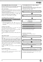
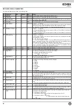
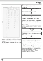
ERASING ALL KEYCODES

To access the “ERASE KEYS” menu, simultaneously press push-buttons 
R + 4 and enter the technical programming password (parameter 8). The 
default value is 123.
The entrance panel initially displays the firmware version then after 10 se-
conds or when a button is pressed it enters the setup menu.

The various submenu items can be scrolled using the “

” and “

” but-

tons. The selectable submenu is indicated by the “

” arrow.

Select the item “ERASE KEYS” and press .
The following message appears:

“ERASE KEYS”

Press a button

1) Keys from keypad.
2) TRANSPONDER

        Press 1 or 2

 “confirmation code”
The entrance panel prompts for the confirmation code before erasing the 
agenda.

Enter code 321 and press 

If the procedure is successful the message “DELETED” appears

The following message appears:

Selecting 1 deletes all of the keys insertable from keypad, selecting 2 era-
ses all TRANSPONDER keys.
After making the selection, the following message appears:

The entrance panel returns to the previous menu

EN

Содержание 1282

Страница 1: ...he Video or audio electronic unit with keypad and graphic display for entrance panels 3 2 1 1 2 3 4 5 6 7 8 9 0 ABC DEF GHI JKL MNO PQRS TUV WXYZ R ART 1282 ART 1282 P 3 2 1 1 2 3 4 5 6 7 8 9 0 ABC DEF GHI JKL MNO PQRS TUV WXYZ R ART 1286 ART 1286 P Manuale installatore Installer guide ...

Страница 2: ...la variazione di questi viene eseguito un controllo di coerenza e nel caso di errore viene generato un messaggio di warning per evidenziare la necessità di regolare i parametri correlati Possibilità di funzionamento a 8 default o 4 DIGIT Possibilità di comporre una targa mista ovvero di aggiungere fino a 31 tasti singoli attraverso i moduli aggiuntivi art 12TS 12TD ad es chia mata diretta alla por...

Страница 3: ...mentazione 3 Morsetto per il segnale fonica verso il montante citofoni monitor 1 Morsetto per il segnale digitale verso il montante citofoni monitor V Morsetto di uscita per segnale video M Morsetto di massa segnale video VL Morsetto alimentazione led illumina zione tasti per moduli supplementari Morsettiera di collegamento OPERAZIONI PRELIMINARI Solo per versioni 1282 P e 1286 P Le unità elettron...

Страница 4: ... 64 32 ON 1 2 16 8 ON 1 2 16 8 ON 1 2 3 128 64 32 ON 1 2 3 128 64 32 ON 1 2 3 16 8 4 ON 1 2 3 128 64 32 ON 1 2 3 16 8 4 ON 1 2 3 128 64 32 ON 1 2 3 16 8 4 ON 1 2 3 128 64 32 ON 1 2 3 16 8 4 ON 1 2 3 128 64 32 ON 1 2 16 8 ON 1 2 16 8 ON 1 2 3 128 64 32 ON 1 2 3 128 64 32 1 3 1 6 Art 12TS o 12TD PROGRAMMAZIONE HARDWARE DEI MODULI PULSANTI SUPPLE MENTARI Eseguire le modifiche con impianto spento ON 1...

Страница 5: ...software ANALYZER fare riferimento all istruzione dell articolo Con la targa spenta collegare l interfaccia art 6952 o 6952 A ai morsetti 1 4 del connettore della targa Se ci sono più targhe connesse in parallelo è possibile programmare la targa lasciandola connessa all impianto se è stato assegnato alla targa un codice parametro codice targa e settando lo stesso valore nel Digibus Address dell An...

Страница 6: ...ica utenti 10 Chiave 0 R1 C 0 1 2 Modalità per l inserimento della chiave per l apertura serratura 0 premere il tasto 0 per poter immettere la chiave 1 premere R ed 1 per immettere la chiave 2 premere il tasto per immettere la chiave 11 Numero digit 4 8 8 Numero di digit utilizzati nella comunicazione digibus È possibile scrivere solo 4 o 8 12 Selez Lingua 0 0 8 Parametro per la selezione della li...

Страница 7: ...impostati siano compatibili con i disposi tivi collegati alle uscite corrispondenti dell alimentatore 29 Abil Finestra Up 0 1 1 Abilita il filtro utente iniziale utente finale anche per i comandi che transitano dal morsetto 1 verso il morsetto 6 della targa 0 No 1 Si 30 Datalogger R9 0 0 1 1 Attiva il datalogger della targa Il datalogger registra il transito dei messaggi sulla linea digibus Per ac...

Страница 8: ...54 Indirizzo Ext 6 0 0 99999999 Indirizzo 6 dispositivo lettura trasponder esterno 55 Indirizzo Ext 7 0 0 99999999 Indirizzo 7 dispositivo lettura trasponder esterno 56 Indirizzo Ext 8 0 0 99999999 Indirizzo 8 dispositivo lettura trasponder esterno 57 Tx Chiave 0 0 3 0 non trasmetto la chiave 1 trasmetto la chiave se è nel database targa 2 trasmetto la chiave se non e nel database della targa 3 tr...

Страница 9: ...n 1 per pulsanti in doppia fila Lo stato di questo parametro fa cambiare l assegnazione del codice hardware ai moduli pulsanti supplementari cifre pre codice 4 p pre codice n nu mero digitato p p p p n n n n Posizione occupata dalle cifre nella composi zione del numero 9 1 1 5 Numero chiamato 9 1 0 0 1 5 Codifica software associazione Hardware software 7 Da uti lizzare solo per versioni 1282 P o 1...

Страница 10: ...to preveda targhe a piè scala complesso edilizio o la presenza del centralino il tempo di attivazione del segnale di chiamata della targa principale deve essere maggiore di 1 secondo rispetto al cor rispettivo tempo impostato sulle targhe a piè scala o sul centralino Negli altri casi il parametro può essere modificato a discrezione dell installatore Nei citofoni in cui la suoneria è generata dal c...

Страница 11: ...ncipale centralino Indirizzo lettore esterno Indirizzo Ext 1 8 49 56 Alla targa si possono collegare fino ad 8 lettori di trasponder tramite il canale digibus montante citofoni morsetto 1 Il codice identificativo dei lettori da cui la targa può ricevere la chiave deve essere programmato in questi parametri Accesso ai parametri nascosti Par nascosti 60 I parametri da 61 a 67 non sono normalmente ac...

Страница 12: ...lizzando i tasti e fino a trovare una chiave libera codice chiave 0 Individuata una chiave libera digitare il codice desiderato e premere per salvare La chiave è memorizzata con i parametri opzionali settati ai valori di default Per modificare una chiave Scorrere la lista delle chiavi fino a quella desiderata Modificare il valore e premere per salvare Scrivendo 0 la chiave viene cancellata La chia...

Страница 13: ...tiva tutti i pulsanti inviando la chiamata con il numero hardware associato al pulsante B se Codifica SW 1 la targa attiva solo i pulsanti che hanno il numero software associato diverso da 0 Ad esempio se il numero software di P1 è 0 quello di P2 è 5 e quello di P3 è 10 la targa attiva solo P2 e P3 ed invia le chiamate con il numero software associato mentre premendo P1 non succede nulla C se Codi...

Страница 14: ... passare al successivo in base al dato modificato Se ad esem pio si modifica l ora digitando un numero maggiore di 2 ad esempio 5 il dato è considerato subito valido e la targa passa al successivo se invece si digita 1 si potrebbe voler scrivere 1 oppure 17 per cui la targa rimane in attesa In questo caso o si digita 01 oppure 1 e si preme il tasto op pure per passare al dato successivo Premendo i...

Страница 15: ...ere più volte il tasto R fino a tornare al menù principale Uso della rubrica Se sono stati memorizzati degli utenti in rubrica è possibile accedervi pre mendo il pulsante oppure il pulsanti e se non sono stati destinati ad altra funzione Premendo il pulsante si accede al menù ricerca della rubrica E pos sibile cercare un utente scorrendo la lista con i tasti e oppure digitando le prime lettere del...

Страница 16: ...rs are cor related when they are modified a consistency check is performed and in the event of an error a warning message is generated to indicate that the correlated parameters must be adjusted Option of 8 default or 4 digit operation Possibility of assembling a composite entrance panel by adding up to 31 individual keys via additional modules type 12TS 12TD e g direct call to switchboard or to o...

Страница 17: ...Terminal for voice signal to interphone monitor cable riser 1 Terminal for digital signal to interphone monitor cable riser V Video signal output terminal M Video signal earth terminal VL Key lighting LED power supply terminal for additional modules PRELIMINARY OPERATIONS only for versions 1282 P and 1286 P Electronic units type 1282 P and type 1286 P can be connected to indivi dual push button mo...

Страница 18: ...with push buttons in single rows there are 6 DIP switches while on 12TD series modules with push buttons in double rows there are 5 DIP switches The DIP switches modify the hardware code of the first push button at the top right of the module The other push buttons are numbered consecutively from top to bottom right to left It is important not to overlap the codes of push buttons on the same panel...

Страница 19: ...the same value in the Analyzer Digibus address Otherwise if using Digibus address 0 the entrance panel must be isolated from the rest of the system by disconnecting the digital signal wire which goes from terminal 1 to the inter phone riser and to the other entrance panels THE PANEL SETUP MENUS To access the entrance panel setup menus simultaneously press push but tons R 4 and enter the technical ...

Страница 20: ...etup menus 09 Agenda Key 1 222 9999 Key for accessing the user agenda management menus 10 Key 0 R1 C 0 1 2 Procedure for inserting the key for the door lock release 0 press 0 to enable the key to be entered 1 press R and 1 to enter the key 2 press to enter the key 11 Digit number 4 8 8 Number of digits used in digibus communication The only possible options are 4 or 8 12 Select Language 0 0 8 Para...

Страница 21: ...l 1 to terminal 6 of the entrance panel 0 No 1 Yes 30 Datalogger R9 0 0 1 1 Activates the panel datalogger The datalogger records the transfer of messages over the digibus line To access the datalogger press R 9 WXYZ 31 View debug 0 0 1 1 activates debug messages displayed from the entrance panel 32 Min LCD Lux 0 5 100 Brightness of the LCD keypad backlight LEDs and additional mo dules with the en...

Страница 22: ...base 2 transmits the key if it is not in the entrance panel database 3 always transmits the key 58 Request Passw 0 0 1 1 requests password confirmation from the transponder reading device 59 Tx UP Down 0 1 1 0 transmits the key on interphone cable riser serial line UP 1 transmits the key to the main entrance panel switchboard DOWN 60 Hidden Paras 0 0 50 Typing 27 enables the display and programmin...

Страница 23: ...d if Para 07 SW encoding is active giving priority to the HW SW association Push buttons in double rows Buttons in two rows 6 For P version entrance panels The parameter must be programmed depending on the layout of the push buttons on the modules with 0 for push buttons in sin gle row and 1 for push buttons in double row The status of this parameter changes the hardware code assigned to additiona...

Страница 24: ... be 1 second longer than the corresponding time set on the stairway entrance panels or on the switchboard In other cases the parameter can be modified at the discretion of the installer In interphones in which the ringtone is generated by the interphone itself such as type 6600 or 7200 the duration of the tone is independent of the parameter set on the entrance panel Answer time 25 This is the max...

Страница 25: ...unication and also frees the interphone cable riser to which it is connected Command repetition Command Rep 63 This command enables the forwarding or repetition of certain special commands as shown in the table below default bit 2 7 8 Tx Key Action 0 Doesn t transmit the key 1 Transmits the key if it is present in the entrance panel data base 2 Transmits the key is it is not present in the entranc...

Страница 26: ...m KEYCODES and press To program a key 6FUROO WKH OLVW RI NH V XVLQJ WKH and buttons until you find a free key keycode 0 IWHU LGHQWLI LQJ D IUHH NH HQWHU WKH GHVLUHG FRGH DQG SUHVV to save The key is memorised with the optional parameters set to the default values To modify a key 6FUROO WKH OLVW RI NH V XQWLO RX ILQG WKH ULJKW RQH 0RGLI WKH YDOXH DQG SUHVV to save Entering 0 deletes the key The key...

Страница 27: ...A If SW encoding 0 the entrance panel activates all push buttons sen ding the call with the hardware number associated with the push button B If SW encoding 1 the entrance panel only activates push buttons which have an associated software number different from 0 For example if the software number of P1 is 0 the number of P2 is 5 and the number of P3 is 10 the entrance panel activates only P2 and ...

Страница 28: ...For example if you modify the hour by entering a number greater than 2 for example 5 the value is considered valid immediately and the entrance panel passes to the next one if however you enter 1 you may want to input 1 or 17 therefore the entrance panel waits for another digit to be entered In this case enter either 01 or 1 followed by the or button to pass to the next value Pressing the button p...

Страница 29: ...e agenda press the R button several times until you return to the main menu Using the agenda If users have been stored in the agenda they can be accessed by pressing the button or the and buttons if they have not been assi gned to another function Pressing the button accesses the agenda search menu It is possible to find a user by scrolling the list with the and buttons or by entering the first le...

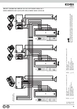
Страница 30: ...a si028 Ref diagram si028 Sezione mm2 Section mm2 0 12 0 25 0 35 0 50 0 75 1 00 1 50 2 50 4 00 6 00 Diametro Diameter mm 0 40 0 58 0 68 0 80 1 00 1 15 1 40 1 80 2 30 2 80 Diametro in decimi Decimal diameter 4 10 6 10 8 10 10 10 12 10 14 10 18 10 5HVLVWHQ D P 5HVLVWDQFH P 14 00 6 60 4 80 3 50 2 20 1 70 1 14 0 69 0 39 0 28 Conduttori Conductors Ø fino a 50 m Ø up to 50 m Ø fino a 100 m Ø up to 100 m...

Страница 31: ...s phone Art 6204 A1 0 Petrarca series phone Art 62K4 A2 6600 series phone Art 6604 AU 6704 AU A3 8870 series phone Art 887B 887B 1 C0 Audio electronic unit with keypad and display Art 1282 CX Entrance panel DX Entrance panel L Electric lock 12V A C P Additional push button for lock A1 Citofono serie Petrarca Art 6204 A1 0 Citofono serie Petrarca Art 62K4 A2 Citofono serie 6600 Art 6604 AU 6704 AU ...

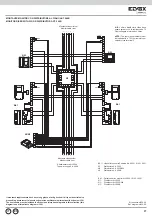
Страница 32: ...foni Interphone cable riser Rete Mains F2 N3 A1 1 A1 1 A3 1 A3 1 A1 1 Petrarca series phone Art 6201 A3 1 8870 series phone Art 8877 C0 Audio electronic unit with keypad and display Art 1282 CX Entrance panel DX Entrance panel L Electric lock 12V A C N3 Distributor Art 949B P Additional push button for lock A1 1 Citofono serie Petrarca Art 6201 A3 1 Citofono serie 8870 Art 8877 C0 Unità elettronic...

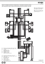
Страница 33: ...ttronica Disconnect the metal jumper located on the side of the terminal block Montante citofoni Interphone cable riser Rete Mains Rete Mains Rete Mains F2 T T Q1 Q1 C0 Audio electronic unit with keypad and display Art 1282 CX Entrance panel F2 Power supply Art 6941 L Electric lock 12V A C P Additional push button for lock T Transformer Art M832 Q1 Relay Art 0170 001 C0 Unità elettronica audio con...

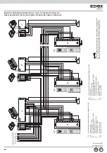
Страница 34: ...fy on the sec ondary entrance panels Par 1 Initial User Par 2 Final User The numbers between initial user and final user of each entrance panel must not be the same as those of an other secondary entrance panel Parameters to modify on the main entrance panel Par 19 Conv Duration The call time of the main entrance panel must be greater than the call time of the secondary panels by at least one seco...

Страница 35: ...nal user of each entrance panel must not be the same as those of an other secondary entrance panel Parameters to modify on the main entrance panel Par 19 Conv Duration The call time of the main entrance panel must be greater than the call time of the secondary panels by at least one second Per la disattivazione del generatore di corrente tagliare il ponticello metal lico J1 posizionato sul retro i...

Страница 36: ...036 N B L ultimo distributore video deve essere caricato con la resistenza da 75 Ohm collegata al morsetto V libero Rif schema si356 00 Ref diagram si0356 00 NOTE The last video distributor must be loaded with a 75 Ohm resistor con nected to free terminal V Montante videocitofoni Monitor cable riser Montante videocitofoni Monitor cable riser All alimentatore Art 6948 To power supply Art 6948 N1 N2...

Страница 37: ...n alternativa allo schema si356 The riser shown must be included in all the video interphone diagrams in this collection this diagram is an alternative to diagram si356 Montante videocitofoni Monitor cable riser Montante videocitofoni Monitor cable riser All alimentatore Art 6948 To power supply Art 6948 N3 N1 N2 B5 1 B2 1 B4 1 B4 1 B4 1 Petrarca series monitor Art 6020 6145 6201 N1 Distributor Ar...

Страница 38: ...ca series monitor Art 6023 6204 6145 Art 6023 6204 6145 B5 Giotto series monitor Art 6344 6354 D0 Video electronic unit with keypad and display Art 1286 DX Entrance panel F1 Power supply Art 6948 L Electric lock 12V A C N1 Distributor Art 5555 N2 Distributor Art 5556 004 P Additional push button for lock B1 Videocitofono serie 7200 Art 7214 B2 Videocitofono serie 6600 Art 6614 6714 Art 6624 6724 6...

Страница 39: ...4 1 B4 1 Petrarca series monitor Art 6020 6145 6201 D0 Video electronic unit with keypad and display Art 1286 DX Entrance panel F1 Power supply Art 6948 L Electric lock 12V A C N1 Distributor Art 5555 N2 Distributor Art 5556 004 N3 Distributor Art 949B P Additional push button for lock B4 1 Videocitofono serie Petrarca Art 6020 6145 6201 D0 Unità elettronica video con tastiera e display Art 1286 D...

Страница 40: ... 1 M 5 8 6 4 Rif schema si037 Ref diagram si037 Montante videocitofoni Monitor cable riser Rete Mains Rete Mains Rete Mains F1 F3 T Q1 Q3 Q3 D0 Unità elettronica video con tastiera e display Art 1286 DX Entrance panel F1 Power supply Art 6948 F3 Addictional power supply Art 6942 L Electric lock 12V A C P Additional push button for lock T Transformer Art M832 Q1 Relay Art 0170 001 Q3 Relay Art 0170...

Страница 41: ...ale I numeri compresi tra utente ini ziale e utente finale di ogni targa non devono coincidere con quelli di un altra targa a piè scala Parametri da modificare sulla targa principale Par 24 Durata suono Il tempo di chiamata della targa principale dev essere maggiore del tempo di chiamata delle targhe a piè scala almeno di un secondo Montante Cable riser Montante Cable riser Montante videocitofoni ...

Страница 42: ... modify on the sec ondary entrance panels Par 1 Initial User Par 2 Final User The numbers between initial user and final user of each entrance panel must not be the same as those of an other secondary entrance panel Parameters to modify on the main entrance panel Par 19 Conv Duration The call time of the main entrance panel must be greater than the call time of the secondary panels by at least one...

Страница 43: ...l User The numbers between initial user and final user of each entrance panel must not be the same as those of an other secondary entrance panel Parameters to modify on the main entrance panel Par 19 Conv Duration The call time of the main entrance panel must be greater than the call time of the secondary panels by at least one second Per la disattivazione del generatore di corrente tagliare il po...

Страница 44: ... F2 and activate function F2 AUDIO ENTRY PANEL VARIANTS Connection of auxiliary functions F1 F2 in systems equipped with internal de coding or without internal decoding In some cases enabling the functions requires the addition of supplementary buttons and connections to be made in addition to the basic connections Interphones type 6204 and 6201 are fitted as standard with only the lock release bu...

Страница 45: ... 6704 AU A3 8870 series phone Art 887B 887B 1 A3 1 8870 series phone Art 8877 B1 7200 series monitor Art 7214 B2 6600 series monitor Art 6614 6714 Art 6624 6724 662D B4 Petrarca series monitor Art 6023 6204 6145 Art 6023 6204 6145 B4 1 Petrarca series monitor Art 6020 6145 6201 B5 Giotto series monitor Art 6344 6354 C Audio electronic unit with push buttons Art 1283 CX Entrance panel D Video elect...

Страница 46: ... V2 I SR V1 VL F1 4 F2 CH V 3 1 M 5 8 6 4 1 3 5 4 CH SR I V SR CH 4 5 3 1 E4 J1 L D M1 V2 I SR V1 VL F1 4 F2 CH V 3 1 M 5 8 6 4 J1 L C M1 V2 I SR V1 VL F1 4 F2 CH V 3 1 M 5 8 6 4 E4 E4 E4 PRI D B A C U I E4 E4 E4 E4 PRI D B A C U I To other modules Agli altri moduli To other modules Agli altri moduli DX DX DX DX The additional power supply type 6582 is used to power the LEDs for the name tags ligh...

Страница 47: ...nel paese dove i prodotti sono installati INSTALLATION RULES Installation should be carried out observing current installation regulations for electrical systems in the country where the products are installed Il prodotto è conforme alla direttiva europea 2004 108 CE e suc cessive Product is according to EC Directive 2004 108 EC and following norms INFORMATION FOR USERS UNDER DIRECTIVE 2002 96 WEE...

Страница 48: ...Vimar SpA Viale Vicenza 14 36063 Marostica VI Italy Tel 39 0424 488 600 Fax Italia 0424 488 188 Fax Export 0424 488 709 www vimar com 49400619A0 00 1311 VIMAR Marostica Italy ...

Отзывы: