Data Logger DL210
Elster-Instromet GmbH
5
2 Formation of the list structure
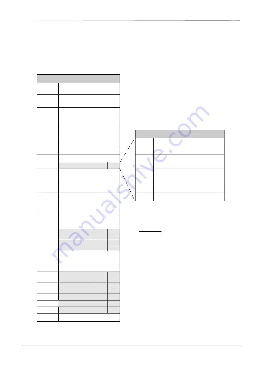
2.1 Summary charts, List Structure (1)
Input I1 is encoder input
Û
Vo
Original counter reading (en-
coder)
or
to
V1
Main counter I1
„User“
V1.A
Adjustable counter I1
Q1
Flow rate I1
L.MI1
Limit for monitoring I1
Md.I1
Mode for I1
MdMI1
Mode for monitoring I1
Submenu U9
SC.I1
Source for monitoring I1
Type
Meter or sensor type
CP.I1
cp value for I1
SN.E
Serial no. of the encoder
SNM
Serial no. of meter on Input 1
Manuf Manufacturer
M.Dat
Meterdata
U9
Med.
Medium
DS.Ca
DS-100 number for V1
SW.Z
Software version
DS.Cb
DS-100 number for V1.P
DateM Date of manufacture
CuNo
Customer number I1
q.max Maximum encoder flow
MP.I1
Measurement period I1
BdEnc Encoder baud rate
MP.Re
Remain'g time in meas. period I1
D
V1MP Incr. meas. period counter I1
D
V1ML Last meas. period value I1
max
V1MP Max. meas. per. counter
Ex current month *
U1
max
V1ML Max. meas. per. counter
Ex last month *
U1
DB.I1
Day boundary for I1
D
V1.Dy Current day counter I1
D
V1D.L Last day value I1
max
V1.Dy Max. day counter I1 cur-
rent month *
U2
max
V1D.L Max. day counter I1 last
month*
U2
ArMo1
Month archive I1
U3
Day value archive I1
U4
ArMP1
Meas. period archive I1
U4
FrMP1
Meas. period archive I1 frozen
Remarks:
·
For meaning of abbreviated des-
ignations: see Chapter 3 and
Appendix C of the manual
·
Submenus are located under "U1"
– "U9" (see Chapter: 2.4.5 of the
manual)
·
*
for flow recording and high flow
display


