page 4
Technical Manual TAR x700-2
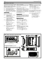
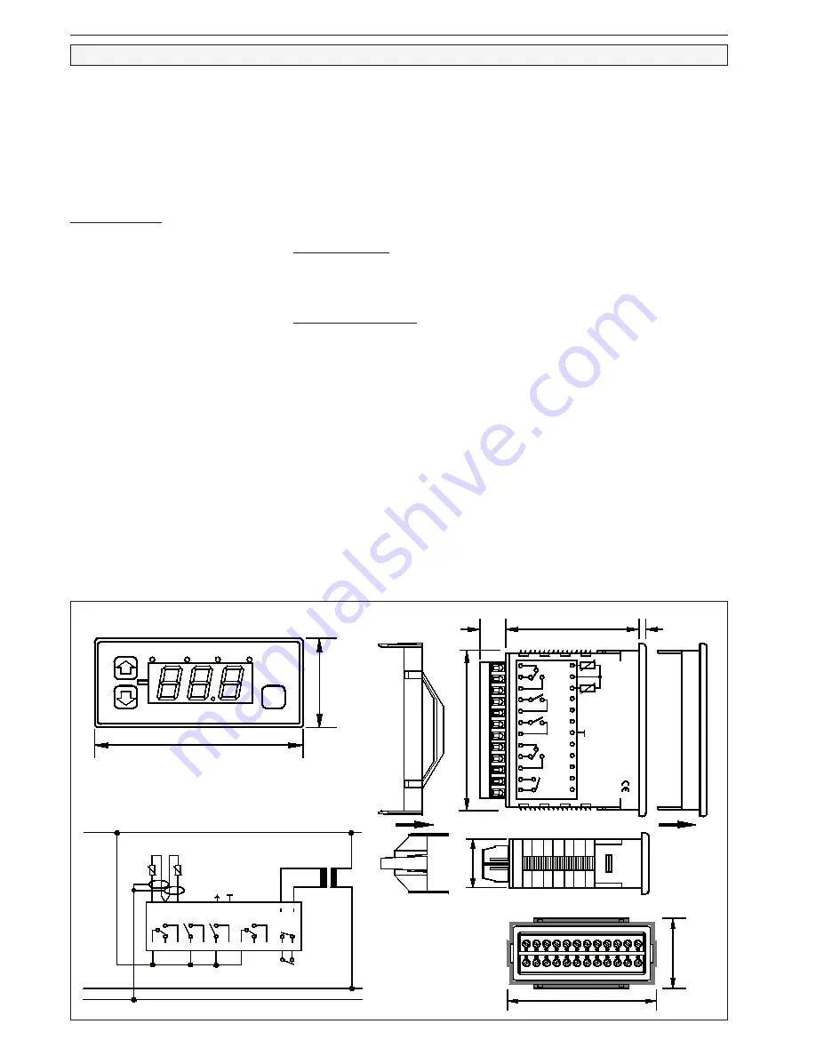
TAR 1700-2 - Dimensions and Connection
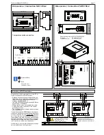
Connection Example
(simplified)
Voltage Output / Analog Output
The TAR contains an analogue 0-10V DC-signal
output. Because the output is scalable, it can be
used either to forward the actual value of sensor 1
(
P01
) or as a proportional /PI-controller output. In
differential control mode the voltage output depends
on the determined differential amount.
P31
...... actual temperature (resp. differential amount)
the output voltage delivers 10V.
P32
...... actual temperature (resp. differential
amount) the output voltage amounts 0V.
P33
...... integral part (I-part) of the output signal in 5
steps from appr. 0,25 to 4 minutes or oFF.
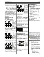
Analog Output Modes
P34
fixes the Analog Output Mode.
P34 = oFF Output is de-activated.
P34 = 1 Output works proportional, that means
rising temperature
-> rising output voltage.
P31/P32
are absolute values.
P34 = 2 Output works anti-proportional, that
means rising temperature
-> falling output voltage.
P31/P32
are absolute values.
P34 = 3 Like P34=1 but the values set by
P31/P32
work relative to the current
setpoint 1 (P04 + offset).
Example:
P31 = 10°C, P32 = -10°C, P34 = 3,
P04 = 15°C, no current shift
Output Voltages:
10V at P04 + P31 = 25°C
0V at P04 - P32 = 5°C
P34 = 4 Like P34=2, but the values set by
P31/
P32
work relative to the
current setpoint 1 (P04 + offset).
Example:
P31 = 10°C, P32 = -10°C, P34 = 4,
P04 = 15°C, no current shift
Output Voltages:
0V at P04 + P31 = 25°C
10V at P04 - P32 = 5°C
Example: Actual value Image
You need a remote display or similar, which shows
-50°C with 0V DC input voltage and +50°C with 10V
DC input voltage:
P32 = "-50", P31 = "+10", P34 must be "1".
Example: Proportional Controller
You want to drive e.g. a motor valve with 0-10V
DC input depending on a temperature. This valve
should be half open at 15°C. If the temperature falls,
the valves should open, if the temperature passes
10°C it must be full open. If the temperature rises,
the valve should be closed, with 20°C and above it
should remain closed.
P32 ="10.0", P31 ="20.0", P34 ="2"
Slow-down time / I-part
P33
(slow-down time) fixes the effect of the I-part
to the control process in 5 steps. The I-part amount
of the controlling variable is identical with the P-part
and will be added. The full size of the I-part will effect
after P33 is run down.
Effects of the Slow-down time
When P34 = 1
Act.Val. = Setpoint: Output 5V ± I-Part
Act.Val. > Setpoint: Output shifts with I-part
to 10V
Act.Val. < Setpoint: Output shifts with I-part
to 0V
When P34=2
Act.Val. = Setpoint: Output 5V ± I-Part
Act.Val. > Setpoint: Output shifts with I-part
to 0V
Act.Val. < Setpoint: Output shifts with I-part
to 10V
When P34 = 3
P31/P32
define a proportional band around the
active setpoint. The output voltage is 10V at
P04
+ P31
and 0V at
P04-P32
.
Act.Val. = Setpoint: Output 5V ± I-Part
Act.Val. > Setpoint: Output shifts with I-Part
to 10V
Act.Val. < Setpoint: Output shifts with I-Part
to 0V
When P34 = 4
P31/P32
define a proportional band around the
active setpoint. The output voltage is 0V at
P04
+ P31
and 10V at
P04-P32
.
Act.Val. = Setpoint: Output 5V ± I-Part
Act.Val. > Setpoint: Output shifts with I-Part
to 0V
Act.Val. < Setpoint: Output shifts with I-Part
to 10V
After an excursive change of the actual value the P-
part is calculated from the max. output voltage and
the proportional band:
Ux = (10V / (|P36 - P37| [K])) * delta Theta [K]
Example: • 10V U
out
at +10°C, 0V U
out
at -10°C
• aimed setpoint 0°C = 5V U
out
• current actual value 0°C
Actual value increases by 2K ->
• U
out
rises to 6V immediately
• U
aus
rises farther, after P38 is run
down, 7V will be reached.
dimensions in: mm (inches)
ELREHA
TAR
76 (3.0)
1
2
3
35
(1
.38
)
P
4
28
(1
.1)
75 (2.95)
Rückansicht m it Befestigungsrahm en
7
4
1
2
3
5
6
19
20
21
22
18
23
24
37
(1
.46
)
8
9
11
10
12
16
17
15 14 13
T AR 1700-2
K 3
K 2
1
N
PE
2
3
K 1
4
6
5
24
L
21
22
23
19
20
0..1
0V
12-24V AC
18-33V DC
50-60Hz
m ax. 5,5V A
12
K 4
9
7
8
10 11
O K1
13
16
DO
ND
O
17
18
15 14
230/24V,
5 VA
probe 1
probe 2
rear view with mounting frame
70
(2
.76
)
11
12
8
10
9
7
6
K3
3
5
4
K2
1
2
12
(.47)
19
0..10V
Te
mp./
Diffe
ren
zreg
ler
Tem
p./
Diffe
ren
ce C
ontr
ol
12-
24V
AC
18-
33V
DC
50/6
0H
z
ma
x. 5
,5V
A
14
13
DI1
NDO
DO
15
16
K4
17
18
E
L
R
E
H
A
24
F1
20
21
F2
22
23
K1
56 (2.2)
3 (.12)


