Technical Manual TAR x700-2
page 3
Functional Description
Signal Input
The controller unit is able to work with the tempe-
rature sensor types TF 201 and TF 501 (Pt1000).
This must be preset by parameter
P25
.
Ranges
:
P25 = 1 (TF 201).......-50...+100°C
P25 = 3 (TF 501/Pt1000).......-100...+300°C
Please note the specific temperature restric-
tions of the different sensor types (e.g.
-40...+80°C with standard-TF-types) and ask
for matching products if necessary.
Actual Value- and Status Display
Temperature values can be displayed in °C or °F. This
will be preset together with the sensor type.
P01
shows the measured value of sensor 1.
If other parameters are selected, 4 minutes after
the last keypress the display switches back to P01
automatically. In operating mode 3+4,
P02
shows
the measured value of sensor 2. In operating mode
'Differential control',
P03
shows additionally the
differential value between sensor 1 and 2.
Display Correction
The Actual Value Display
P01
can be calibrated by
P23,
P02
can be calibrated by
P24
.
Operating Modes
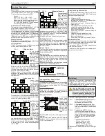
The TAR controller knows 4 different operating
modes, which can be preset by
P19
:
P19 = 1:
3 Alarm
.
In this mode
you realize a 3-
stage controller,
relay K4 works
as a closed cir-
cuit alarm relay,
sensor input 2 is
disabled.
The value of
sensor 1 will be
compared with
P04, P05
and
P06
, the relays K1, K2 or K3 switch depending on
the deviation. P04 is always an absolute value, the
following setpoints can be either relative values or
absolute values (preset by
P08
).
Relative values = Stage switches in a specific
distance to the leading setpoint P04. If P04 will be
changed, the relative setpoints will be changed the
same amount.
P19 = 2 :
4-stage controller
Sensor input
2 is disabled
in this mode.
The value of
sensor 1 will be
compared with
P04, P05, P06
and
P07
, the
relays K1, K2,
K3 or K4 switch
depending on
the deviation.
Control setpoint 1 (P04) is always an absolute value,
the following setpoints can be either relative values
or absolute values (preset by
P08
).
P19 = 3 :
Double 2-Stage Controller
Sensor 1 af-
fects on the
control set-
points
P04/
P05
(= relays
K1/K2 = control
circuit 1).
P04 is the lea-
ding setpoint of
control circuit
1, control set-
point 2 (P05)
can be either absolute or relative (
P08
). Sensor 2
affects on the control setpoints
P06/P07
(= relays
K3-K4 = control circuit 2). P06 is the leading setpoint
of control circuit 2, P07 can be either absolute or
relative (
P08
).
P19 = 4
Differential Controller
The calculated dif-
ferential amount
from "sensor 1
minus
sensor 2"
will be compared
with
P04
.
Relay K1 swit-
ches, if the pre-
set value
P04
+
hysteresis
P18
is reached. The
relay switches off
again, if the dif-
ferential amount
decreases and reaches P04. The stages 2 (
relay
K2, P05, assigned to sensor 1
) and 3 (
relay K3,
P06, assigned to sensor 2
), can work independly
as single stage controllers.
Relay K4 works as a closed circuit alarm relay.
Switching Hysteresis
With
P18
you set a switching hysteresis, which
affects to all setpoints. The position of this hyste-
resis (above/below the setpoint) depends on the
selected switching characteristics (
P10
-
P13
) of
the single relays.
Setpoint Limits
To prevent that the final user adjusts the setpoints
to an inadmissible value, the setpoint range can be
limited by
P16
and
P17
.
Real time clock
The integrated real time clock allows to change the
setpoints at specific times. The timer has a power
backup for about 10 days in case of power failure.
The time of the day and the date can be set with
parameters
P35
...
P36
.
Because the display has only three digits, the time
value comes in the following format:
Day-/Night Mode / Setpoint Offset
Initiation by real-time clock
With
P14/P15
you can set a period of time within
all setpoints will be shifted by the amount of
P09
.
If not necessary, you can disable P14/P15 (display
shows "
oFF
").
Initiation by Digital Input
Digital Input OK 1 can also be programmed to
activate this offset (
P29=1
). An active 2nd setpoint
is indicated by a flashing decimal point.
Temperature Alarm
If the tempe-
rature value
measured with
sensor 1 ex-
ceeds the ran-
ge set by
P27
and
P28
, the
alarm relay will
be activated
after the delay
timer
P26
is run
down.
Parameter
P21
shows the remaining time up to
an alarm.
P28 (lower limit) is an absolute value, P27 is always
a relative value in a distance to the actual setpoint
1 (P04 + potential shift).
3rd Position=
minutes x 10
1st and 2nd
Position=
hours
Relay Switching Characteristic
The Switching Characteristic of the relay K1-K4 is
defined by the parameters
P10...P13
. The following
characteristics are possible:
1= Refrigeration (RF)
Used for standard applications (e.g.
temperatures above 0°C). The load would be
switched by the N/O-contact.
Actual value = se hysteresis: Relay on
2 = Freezing (FR)
The load would be switched by the N/C-
contact, this enables that the load will be
switched on permanently in case of mains
loss or controller defect.
Actual value = se hysteresis: Relay off
3 = Heating (HT)
Usable for heating applications. Load
would be switched off in case of mains
fail or controller defect.
Actual value = setpoint
-
hysteresis: Relay on
Minimum Idle-Time
If a load is switched off by a relay, this relay cannot
be switched on again before the time set with
P20
is over. P20 affects all relay stages.
The indicator LED's of the single stages flashes
while this idle time runs.
The Minimum Idle-Time affects immediately after
power-on of the controller.
Digital Input
Digital input DI1 is normally connected to mains
voltage. If this voltage is interrupted, the function set
with
P29
will be initiated after a time delay (
P30
).
P30
is adjustable within 0...99 minutes, but at '0' the
minimum delay is appr. 4 seconds.
P29=oFF Digital input DI/OK 1 is de-activated
P29=1
Control Setpoint 2
(night-setpoint) is
active. The setpoints increase/
decrease by the amount of P09.
P29=2
An
external alarm
is detected after
P30 is run down. LED 4 and the alarm
relay are activated after P26 has been
run down.
P29=3
Controller unit oFF
. All control
functions will be disabled, the display
shows "oFF". This allows to switch off
the unit without an alarm message in
a network. Relays 1-3 are deactivated,
the alarm relay remains in a neutral
position.
Analogue output behaviour:
• Delivers 0V with op-mode
proportional (P34=1 or 3).
• Delivers 10V with op-mode
anti-proportional (P34 = 2 or 4)
P22
shows the remaining delay time of the digital
input.
Using the
TAR 1700-2
this function must
be started by opening an external, potential
free contact connected to terminals 11/12.
Never connect mains voltage to these
terminals, danger of destruction!
This
contact must be suitable for 5VDC/1mA.
K4
K3
P06
K2
P05
sens2
sens1
K1
P04
K4
K3
P07
P06
K2
P05
sens2
P04
K1
sens1
K2
P05
K4
K3
P06
P07
sens2
control circuit 1
control circuit 2
sens1
K1
P04
K4
K3
P06
K2
P05
sens2
K1
P04
Diff.
sens1
alarm after P26 is run down
alarm after P26 is run down
tem
per
atu
re p
rofi
le
Upper AT
P27
(relative)
Lower AT
P28
(absolute)


