page 6
Technical Manual TAR x700-2
CONNECTION INFORMATION & SAFETY INSTRUCTIONS
The guarantee will lapse in case of damage caused by failure
to comply with these operating instructions! We shall not be
liable for any consequent loss! We do not accept liability for
personal injury or damage to property caused by inadequate
handling or non-observance of the safety instructions!
The guarantee will lapse in such cases.
This manual contains additional safety instructions in the
functional description. Please note them!
If you notice any damage, the product may not be connected
to mains voltage! Danger of Life!
A riskless operation is impossible if:
• The device has visible damages or doesn't work
• After a long-time storage under unfavourable conditions
• The device is strongly draggled or wet
• After inadequate shipping conditions
• Never use this product in equipment or systems that are
intended to be used under such circumstances that may
affect human life. For applications requiring extremely
high reliability, please contact the manufacturer first.
•
The product may only be used for the applications
described on page 1.
• Electrical installation and putting into service must be
done from qualified personnel.
•
During installation and wiring never work when the
electricity is not cut-off ! Danger of electric shock!
•
Never operate unit without housing.
Danger of electric shock!
•
All ‘PE’ terminals must be connected to ground.
Danger of electric shock!
Additionally, the internal noise
filter will not work, faulty indicated values may occur.
• Please note the safety instructions and standards of your
place of installation!
• Before installation: Check the limits of the controller and
the application (see tech. data). Check amongst others:
- Make sure that all wiring has been made in accordance
with the wiring diagram in this manual.
- Supply voltage (is printed on the type label).
- Environmental limits for temperature/humidity.
- Maximum admitted current rate for the relays. Compare
it with the peak start-up currents of the controlled loads
(motors, heaters,etc.).
Outside these limits malfunction or damages may occur.
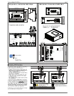
• Sensor/probe cables must be shielded. Don’t install them
in parallel to high-current cables. Shielding must be
connected to PE at the end close to the controller.
If not, inductive interferences may occur.
• Please note for elongation: The wire gauge is not critical,
but should have 0,5mm² as a minimum.
• Mounting the controller close to power relays is
unfavourable. Strong electro-magnetic interference,
malfunction may occur!
• Take care that the wiring of interface lines meets the
necessary requirements.
• All used temperature sensors must be identical. Never
use different types at the same time. This will not work.
• TF-type sensors are not designed for being immersed in
fluids permanently. In such a case, always use dip-fittings.
With extreme temperature variations, the sensor may be
damaged.
Cleaning
The use of a dry, lint-free cloth and household agents is sufficient
to clean the product.
Never use acids or acidic fluids! Risk of damage!
Installation / Start-up
Read Safety Instructions !
If the TAR unit is switched ON, the display shows
the actual value of sensor 1. At first you have to set
the basic parameters:
•
Enter Access Code '70' at P41
•
Operating mode (P19)
•
Type of used sensor (P25)
•
Enter Access Code '88' at P40
•
Switching characteristic of the relays
(P10-P13)
•
Task of control input DI1 (OK1) (P29)
•
If the unit is networked:
Address in network (P39) and Baudrate (P38)
•
Function of the Analogue Output (P31 - P34)
This was the basic configuration, now you can enter
the specific setpoints, times, etc.
Installation hint:
If the measured values 'jump' check the
following: Is the shielding of the sensor
wire connected to PE near the controller
unit? Is the PE terminal of the controller
unit connected to PE? If the sensor wire
is shielded correctly but the value on the
display continues 'jumping', please try
to solve the problem by removing the
shield from PE and connecting it to a
ground terminal of the TAR.
Display Adjust
To calibrate the two actual value displays, use para-
meters
P23
resp.
P24
to correct the value.
original set up: 9.3.18, tkd/jr
checked: 12.3.2018, ek/ha approved: 12.3.2018, mv/mh transl.():
corr:
For the devices
TAR 1700-2, TAR 3700-2 and TAR 5700-2 we state the following:
When operated in accordance with the technical manual, the criteria have been met that are outlined in the EMC Directive
2014/30/EC and the Low Voltage
Directive
2014/35/EC. This declaration is valid for those products covered by the technical manual which itself is part of the declaration.
Following standards were consulted for the conformity testing to meet the requirements of EMC and Low Voltage Guidelines:
EN 55011:2016, EN 61010-1:2010, EN 61326-1:2013
CE marking of year: 2017
This statement is made for the manufacturer / importer
by:
ELREHA Elektronische Regelungen GmbH
Werner Roemer,
Technical Director
D-68766 Hockenheim
www.elreha.de
Hockenheim
......
12.6.2017
.................................................................
(
Name / Address
)
C
ity Date
S
ignature
EC Declaration of Conformity


