CAN Interface
The MC9S12DP512 contains five independent CAN-Modules,
designated as CAN0 to CAN4.
CAN0 communicates over MCU pins PM0 and PM1 with IC5,
which serves as the CAN bus physical interface. CAN bus signals
CANH und CANL can be accessed at X4/63 and X4/64.
R9 determines the slope control setting for the CAN bus signals. To
operate IC5 in High Speed mode, R9 must be shorted (refer to the
PCA82C251 data sheet for details).
R8 is a termination resistor, required if the S12compact is the last
node in a CAN bus chain. BR2 should be closed in this case, otherwise
opened.
For CAN1 to CAN4, no physical drivers are provided on the
S12compact. They can be added externally, if required.
TTL signals für CAN1 to CAN3 are available at Port M. Please
refer to the schematic diagram to see if other functions (which share the
same pins) are needed in your application. TTL signals for CAN4 are
available through port pins PJ6 and PJ7. However, in this case a
conflict with the IIC-Bus will occur, since both functions share the
same two pins. If IIC and CAN4 have to be used at the same time,
CAN4 can be re-routed to port pins PM4/5 or PM6/7 by setting the
re-routing control register MODRR accordingly (which, in return, may
have an influence on using an IF-Module or the USB interface option).
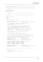
The following listing demonstrates a number of basic functions for
CAN communication:
S12compact
34


