


Indicator-LED
The logic level of port pin PE7 is latched at the rising edge of reset
and provides the control signal /XCLKS. This signal is used to select
one of two possible clock configurations for the MC9S12DP512. High
level activates the integrated Colpitts oscillator. After reset, PE7 can be
used as a general-purpose I/O-pin. On the S12compact, this signal is
used to control the indicator LED D2, driven by buffer IC6C.
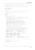
To turn the LED on or off, some simple macros can be used, as
shown in the following C header file:
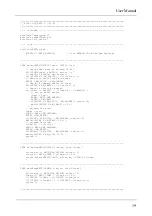
//=============================================================================
// File: S12CO_LED.H - V1.00
//=============================================================================
#ifndef __S12CO_LED_H
#define __S12CO_LED_H
//-- Macros -------------------------------------------------------------------
#define initLED() PORTE |= 0x80; DDRE |= 0x80
#define offLED() PORTE |= 0x80
#define onLED() PORTE &= ~0x80
#define toggleLED() PORTE ^= 0x80
//-- Function Prototypes ------------------------------------------------------
/* module contains no code */
#endif //__S12CO_LED_H ========================================================
Buzzer
The sound transducer (buzzer) SP1 is driven by buffer IC6D and
controlled by the MCU's port pin PT2, provided the solder bridge BR3
is closed.
PT2 is connected with one of the eight timer channels of the MCU.
Frequency generation is realized using the Output-Compare function of
the timer system.
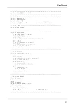
The following example demonstrates, how Output-Compare inter-
rupts can be used to generate oscillations in the audible range:
S12compact
20


