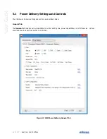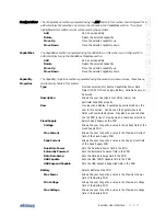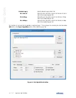
Connections and Indicators
| 23 of 157
Ellisys USB Explorer 350
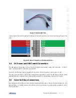
Figure 9 Flying Leads Probe
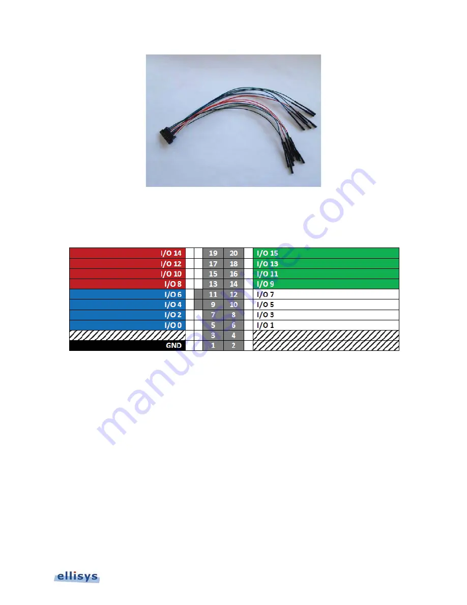
Figure 10 below illustrates the polarized female plug on the probe as well as wire colors (view is facing the end of the
plug).
Figure 10 View of Connector on Flying Leads Probe
3.4
DC Power and USB Control Connection
The USB Explorer 350 provides a DC Input Jack for supplying unit operating voltage and Vbus power. A USB 3.1
(Gen 1) port is provided for connection to a control PC.
An external 24VDC power supply is supplied with the system. The unit requires a minimum power of 18W.
The USB control connection is used by the connected Ellisys application to control the USB Explorer 350 and upload
captured data when in Analyzer mode. Captured data is streamed to the hard drive on the Control Computer.
3.5
Inter-Unit Sync Connections
The USB Explorer 350 provides two Micro A/B USB receptacles that are used to time-synchronize multiple units. This
approach allows for multiple captures from different units to be displayed in a single Analyzer application, with a
common time base.
Содержание USB Explorer 350
Страница 1: ...Ellisys USB Explorer 350 User Manual Version 0 83 October 30 2015...
Страница 36: ...36 of 157 Exerciser User Interface User Guide Figure 13 Source Capabilities Interface...
Страница 41: ...Exerciser User Interface 41 of 157 Ellisys USB Explorer 350 Figure 16 Edit VDM Modes...
Страница 45: ...Exerciser User Interface 45 of 157 Ellisys USB Explorer 350 Figure 19 USB Power Delivery BIST Tab...
Страница 61: ...Examiner User Interface 61 of 157 Ellisys USB Explorer 350 Figure 31 Examiner Settings Tab...
Страница 86: ...86 of 157 Managing Analyzer Recordings User Guide...
Страница 138: ...138 of 157 Analyzer Protocol Error Verifications User Guide...
Страница 154: ...154 of 157 Web Control User Guide 24 Web Control This feature is current disabled Contact Ellisys for further details...
Страница 157: ......

