background image

Connections and Indicators

  |  17 of 157

Ellisys USB Explorer 350

3.

Connections and Indicators 

The USB Explorer 350 includes various receptacles on all four sides, and a set of four multi-color LEDs on the top 
that provide various capture, generate, input power, and control connection indications.  

For Type-C applications, an externalized Type-C connection is provided through use of a supplied custom “Y” cable 
and associated adapters.

3.1

Standard-A and Standard-B Receptacles

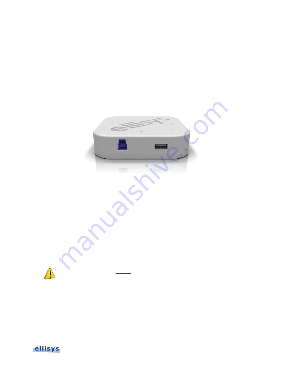
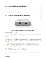
Figure 5 USB Explorer 350 Standard-A and Standard-B Receptacles

Upstream (Standard-B) Receptacle

The Upstream connector is usually used to connect the USB Explorer 350 to a host or a downstream-facing port on a 
hub (for USB 2.0 or 3.1 applications).  For USB Type-C applications, this receptacle is connected to the supplied 
custom “Y” cable.  

Downstream (Standard-A) Receptacle

The Downstream connector is usually used to connect the USB Explorer 350 to a device or an upstream-facing port 
on a hub (for USB 2.0 or 3.1 applications).  For USB Type-C applications, this receptacle is connected to the supplied 
custom “Y” cable.

When connecting USB cables DO NOT force the connector into the unit. The metal part of the 
connector should not be inserted completely into the connection port. Forcing the connector or 
inserting all of the metal part of the connector can break the port connection and is not covered 
by the warranty.

3.2

LED Indicators on Unit and Adapter

The USB Explorer 350 provides four multi-color LEDs on the top of the unit for various statuses and indications
regarding input power, the USB control connection, multi-unit synchronization, and traffic being captured or 
generated.  

Содержание USB Explorer 350

Страница 1: ...Ellisys USB Explorer 350 User Manual Version 0 83 October 30 2015...

Страница 2: ...ty is assumed with respect to the use of the information contained herein Ellisys assumes no responsibility for errors or omissions contained in this book This publication and features described herei...

Страница 3: ...e shipped at Ellisys expense Repaired or replacement product will continue to be covered by this limited warranty for the remainder of the original warranty or 90 days whichever is longer Limitations...

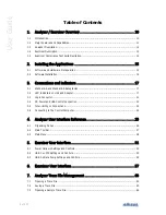
Страница 4: ...acles 17 3 2 LED Indicators on Unit and Adapter 17 3 3 Logic Connector 21 3 4 DC Power and USB Control Connection 23 3 5 Inter Unit Sync Connections 23 3 6 Connecting to the Control Computer 24 4 Anal...

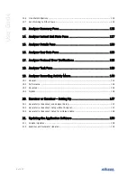
Страница 5: ...ssive Tapping to Board 83 10 Managing Analyzer Recordings 84 10 1 Setting the Recording Options 84 10 2 Selecting an Analyzer 90 10 3 Initiating a Recording 91 10 4 Stopping a Recording 91 10 5 Restar...

Страница 6: ...tions 135 18 Analyzer Task Pane 139 19 Analyzer Recording Activity Menu 140 19 1 General 141 19 2 Performance 142 19 3 Advanced 144 19 4 Options 145 20 Exerciser or Examiner Setting Up 147 20 1 Genera...

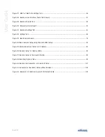
Страница 7: ...Fying Leads Probe 23 Figure 10 View of Connector on Flying Leads Probe 23 Figure 11 USB Explorer 350 Exerciser Interface 31 Figure 12 USB Power Delivery General Tab 34 Figure 13 Source Capabilities I...

Страница 8: ...ure 33 Basic Analyzer Setup 79 Figure 34 Basic Analyzer Setup Using Standard USB Cables 80 Figure 35 Alternate Analyzer Setup for CC Capture 81 Figure 36 Analyzer Setup for Captive Cable 82 Figure 37...

Страница 9: ...ise A tip symbol tells you information that will help you carry out a procedure Where to Find More Help Go to the Ellisys website and the following pages for the latest information Ellisys products pa...

Страница 10: ...mands and responding to them The Examiner compliance test suite provides various tests for DisplayPort Alternate Mode operation Support for other Alternate Modes may be added please check with Ellisys...

Страница 11: ...to provide the major features and capabilities listed below To see a list of features enabled on your USB Explorer 350 please check the Help menu with the unit connected to your PC over USB Certain f...

Страница 12: ...raffic such as DisplayPort and or USB 3 1 Gen1 and Gen2 traffic and bus events occurring between two USB system components such as a host and device or a provider and consumer and presents comprehensi...

Страница 13: ...s are typically used one to act as the Exerciser and the other to act as Analyzer capturing traffic between the Exerciser and the device under test DUT for debug and characterization purposes 1 5 Exam...

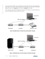
Страница 14: ...er the control of the Analyzer application directly when the Analyzer checkbox in Examiner s Settings tab is unchecked Figure 3 and Figure 4 below depict a simplified setup for Exerciser mode or Exami...

Страница 15: ...Intel Core 1 5 GHz or compatible processor or better 512 MB RAM or more 1280 x 1024 screen display resolution with 65 536 colors or better USB 2 0 Host Controller USB 3 1 Gen1 recommended The USB Expl...

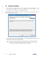
Страница 16: ...Setup Wizard screen appears Analyzer installation is shown below Exerciser and Examiner applications will vary accordingly 2 Follow the dialog prompts to install the software application Note that de...

Страница 17: ...Type C applications this receptacle is connected to the supplied custom Y cable Downstream Standard A Receptacle The Downstream connector is usually used to connect the USB Explorer 350 to a device o...

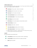
Страница 18: ...Connections and Indicators User Guide In addition the Type C Adapter includes two LEDs that provide various indications specific to port connection statuses LEDs on the USB Explorer 350 Figure 6 LED...

Страница 19: ...operating Green blinking Powered but not connected White blinking Driven by software applications when serial number is selected Red blue blinking Power failure Red steady Application active memory fu...

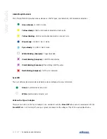
Страница 20: ...de White blinking Analyzer Trigger detected Violet blinking Analyzer USB PD data detected Violet blinking Exerciser Transmitting USB PD packet Red blinking Analyzer Traffic error detected Sync LED The...

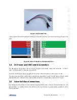
Страница 21: ...a valid connection voltage cRd Connect 0 25V 2 04V 3 3 Logic Connector The logic connector exposes 20 pins 2 rows of 10 pins each spaced at 1 27mm x 1 27mm A ground is provided along with 16 input ou...

Страница 22: ...custom cable or adapters GND and I O 15 are reserved for this purpose In these cases control of resistors Rp and Rd are left to the control of the user and are not controlled by the USB Explorer 350 o...

Страница 23: ...ded for connection to a control PC An external 24VDC power supply is supplied with the system The unit requires a minimum power of 18W The USB control connection is used by the connected Ellisys appli...

Страница 24: ...r 350 to a SuperSpeed USB USB 3 0 USB 3 1 port on the Control Computer to obtain optimal performance Installing the USB Driver The precise installation procedure for the USB driver will vary according...

Страница 25: ...and Gen 2 traffic USB 2 0 Overview Displays a chronological record of bus traffic and events for USB 2 0 traffic USB PD Overview Displays a chronological record of bus traffic and events for USB Power...

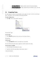
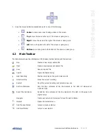
Страница 26: ...ormation on saving display preferences To open or display a pane 1 Select View in the menu and select the desired pane The selected pane opens To close a pane 1 Click on Close positioned at the top ri...

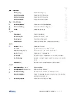
Страница 27: ...ns and their actions New Creates a new empty capture file Open Opens a previously saved capture file Save Saves a capture file Search Opens the Search dialog Start Recording Starts a recording on the...

Страница 28: ...o retrieve a shared capture from the Ellisys cloud Import Ctrl P Imports a file to view in the Analyzer application Export Ctrl E Exports a trace to various formats Switch Workplace Allows user to swi...

Страница 29: ...ayout excluded Search Search CTRL F Opens the Find menu Search In Specifies the Overview in which to search Instant Search CTRL I Places the cursor in the Instant Search window Go To CTRL G Opens the...

Страница 30: ...350 Set Time Reference CTRL T Sets the time reference at the line selected in the active Overview at 0 000 000 000 Reset Time Reference CTRL SHFT T Resets the time reference at the line selected in t...

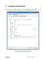
Страница 31: ...er Interface The user interface of the USB Explorer 350 Exerciser uses a tabular approach to expose features available for USB 3 x and USB Power Delivery Various tabs are displayed These will vary dep...

Страница 32: ...tions status indications links to execute common commands physical media FSK or BMC and starting role selections Commands Tab Provides a list of commands that can be selected and executed Checks Tab L...

Страница 33: ...des a list of editable timing interval and count parameters LFPS sequences link training ordered sets scrambling SKP controls and spread spectrum clocking SSC enable disable Settings Tab Shows all ava...

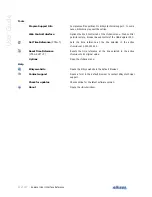
Страница 34: ...ols The USB Power Delivery settings and controls are described below General Tab The General tab includes various selections to control starting role power capabilities and VDM features Various comman...

Страница 35: ...for the Exerciser s Source Capabilities and allows for editing of these capabilities using Edit button Sink Cap Displays the current selection for the Exerciser s Sink Capabilities and allows for edi...

Страница 36: ...36 of 157 Exerciser User Interface User Guide Figure 13 Source Capabilities Interface...

Страница 37: ...ed Description Allows the user to assign a text string name to a particular capability property Raw Hex input and display Populated by entries made by the user in this section Can be used to populate...

Страница 38: ...ws the user to specify a value in the Minimum Voltage field of the Variable Supply PDO Max Voltage Allows the user to specify a value in the Maximum Voltage field of the Variable Supply PDO The Interf...

Страница 39: ...ring name to a particular capability property Raw Hex input and display Populated by entries made by the user in this section Can be used to populate reserved fields with non default values May also b...

Страница 40: ...Variable Supply PDO The Interface for defining the Exerciser s VDM Identity is illustrated below This is accessed by selecting the Identity Edit button in the VDM Configuration section of the USB PD...

Страница 41: ...Exerciser User Interface 41 of 157 Ellisys USB Explorer 350 Figure 16 Edit VDM Modes...

Страница 42: ...F2 or by selecting the Execute F2 button on this page Various attributes are available for each command selected such as repetitions SVIDs and other appropriate fields These attributes are displayed...

Страница 43: ...ab provides the user the option to have the Exerciser monitor the traffic sequences or events and then provide go and no go indications on such sequences and events should they occur These checks are...

Страница 44: ...he current Sink Capabilities and provides an Edit button to change these settings Vendor ID Vendor ID Input Externally Powered TBD Test Modifiers TBD Checks Results The Check Results section lists sev...

Страница 45: ...Exerciser User Interface 45 of 157 Ellisys USB Explorer 350 Figure 19 USB Power Delivery BIST Tab...

Страница 46: ...nal that will allow measurement of the eye pattern and of the spectrum mask Carrier Mode 0 The Exerciser sends a continuous string of 0 s Mode 1 The Exerciser sends a continuous string of 1 s Mode 2 T...

Страница 47: ...t physical parameters as well as parameters used by the Ellisys stack These selections allow for corner case testing of certain timers counters signaling voltages and the bit rate An ability to limit...

Страница 48: ...set Resets the amplitude and bit rate settings to nominal values Custom Stack Parameters Parameter Spec Reference tReceive 6 5 1 tSenderResponse 6 5 2 tSourceActivity 6 5 3 1 tSinkActivity 6 5 4 1 tSe...

Страница 49: ...lorer 350 units A selection is available to keep the Exerciser GUI on top of other windows and another selection allows for the selection of window transparency Placing the mouse pointer over a serial...

Страница 50: ...rciser User Interface User Guide 5 2 USB 3 x LFPS Settings and Controls General Tab The USB 3 x LFPS General tab includes various selections to control LFPS parameters Figure 22 USB 3 x LFPS Settings...

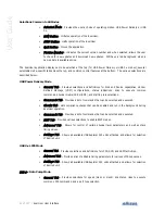
Страница 51: ...in Type field to be sent up to 64K Sent Indicates a running count of patterns transmitted L LFPS Settings tBurst Provides for definition of LFPS tBurst duration tRepeat Provides for definition of LFP...

Страница 52: ...of 157 Exerciser User Interface User Guide Advanced Tab The USB 3 x LFPS Advanced tab allows the user to control the Exerciser s various LFPS timing characteristics Figure 23 USB 3 x LFPS Advanced Ta...

Страница 53: ...plorer 350 units A selection is available to keep the Exerciser GUI on top of other windows and another selection allows for the selection of window transparency Placing the mouse pointer over a seria...

Страница 54: ...Settings and Controls General Tab The General Tab provides basic settings to control the Exerciser s mode Various command execution links are available as well as a port type selection host or device...

Страница 55: ...vanced Tab provides various controls relating to the Exerciser s link training SKP Rates and other behaviors and characteristics Settings can be saved and loaded as needed Settings can also be individ...

Страница 56: ...nits A selection is available to keep the Exerciser GUI on top of other windows and another selection allows for the selection of window transparency Placing the mouse pointer over a serial number in...

Страница 57: ...er the user would set up as the Exerciser mode either direct from the Examiner unit to the UUT or with the analyzer in between the Examiner unit and the UUT See Section 20 Exerciser or Examiner Settin...

Страница 58: ...b indicates the present version and may also be clicked by the user to check for availability of new application updates Tests are initiated with the Run button which also provides an alternate select...

Страница 59: ...If an analyzer was used selected in the Settings tab a Traces button also appears when testing completes so the user may open traces of interest a trace is saved for each test executed Traces may als...

Страница 60: ...t serial number Reports created at the end of test execution are stored in the directory specified by the user in the Browse box If an analyzer unit is also used associated analyzer traces are also st...

Страница 61: ...Examiner User Interface 61 of 157 Ellisys USB Explorer 350 Figure 31 Examiner Settings Tab...

Страница 62: ...tics which are confirmed in the Consistency tests available on the Tests tab The characteristics can be imported from a text file using the Load from File selection and saved using the Save selection...

Страница 63: ...the menu or click on Open The Open menu appears 1 Select the file required and click Open The selected file opens in the software Sample captures are available from File Load Sample 7 2 Saving a Trace...

Страница 64: ...les are included with the application To open a sample file 1 Select File Load Sample in the menu 2 Click on the desired sample 7 4 Printing a Trace File Use the Page Setup option File Page Setup to s...

Страница 65: ...s USB Explorer 350 The Print preview window appears 2 Print directly from the Print preview window using the print icon Or Click on Close to return to the trace file To print a file 1 Select File Prin...

Страница 66: ...orting Data to View in a Trace File The application permits the user to import data from formatted text files for display in the Ellisys viewer format The Analyzer hardware is not required for these o...

Страница 67: ...he desired import option 2 Click on Next then follow the prompts to define the import desired 7 6 Exporting a Trace File A trace file can be exported for various ancillary purposes and in several form...

Страница 68: ...68 of 157 Analyzer Trace File Management User Guide The Export menu appears 2 Select the desired Export option 3 Click on Next and follow the prompts the complete the desired export...

Страница 69: ...tions options A default Workspace is provided by the application but users may create and save new Workspaces as desired A non exhaustive list of items affected by Workspace setting is shown below Gen...

Страница 70: ...g default settings to establish a new Workspace based on the default settings Or Select Create using current workspace s settings to establish the new workspace based on the current settings 4 Select...

Страница 71: ...a Workspace 1 Select File Switch Workspace from the menu The Workspace menu appears 2 Select the Workspace name drop down arrow 3 Select the desired Workspace name 4 Click on Remove 5 Click on OK To...

Страница 72: ...72 of 157 Analyzer Workspaces and Layouts User Guide The Import and Export Settings Wizard menu appears 2 Select Export settings 3 Click on Next...

Страница 73: ...ect Export all workspace s setting Or Select Export only the selected categories of settings below and check the desired categories 5 Select Browse to specify a location to name and save the file 6 Cl...

Страница 74: ...74 of 157 Analyzer Workspaces and Layouts User Guide The Import and Export Settings Wizard menu appears 2 Select Import settings 3 Click on Next...

Страница 75: ...4 Select Import all settings Or Select Import only the selected categories of settings below and check the desired categories 5 Select Browse to specify a location to name and save the file 6 Click on...

Страница 76: ...76 of 157 Analyzer Workspaces and Layouts User Guide The Import and Export Settings Wizard menu appears 2 Select Restore default settings 3 Click on Next...

Страница 77: ...nd position of the application s various panes and windows Layouts can also be used to customize which panes and windows are displayed On installation of the Analyzer application a default layout is p...

Страница 78: ...ut Reset Layout from the menu The layout is reset to the factory default To delete a layout 1 Select Layout Delete Layout from the menu The active layout is deleted and removed from the layouts listed...

Страница 79: ...orts such as between a device and a host or between a Provider and a Consumer etc This is shown below in Figure 33 Basic Analyzer Setup The supplied 24VDC Power Supply is not shown below but is requir...

Страница 80: ...dard USB cables is as shown below The supplied 24VDC Power Supply is not shown below but is required Note that the use of the word Device in the figure below is generic these may be a USB host a USB p...

Страница 81: ...tup approach using the supplied Type C to Type C adapter and jumper wires to connect to the Configuration Channel CC wire and Ground The supplied 24VDC Power Supply is not shown below but is required...

Страница 82: ...dware Setup Devices with Captive Cable When analyzing a device that employs a captive cable it is necessary to use the supplied Type C to Type C adapter as shown in Figure 36 Analyzer Setup for Captiv...

Страница 83: ...etup Passive Tapping to Board The Analyzer can be used to tap directly to a board such as boards that are typically used during early development stages This setup is depicted below in Figure 37 Analy...

Страница 84: ...tics of the Analyzer hardware during a recording Options selected in the Recording Options menu are critical Captures with errors or missing data may reflect incorrect settings Review these settings c...

Страница 85: ...tics Enables the recording of Vbus Voltage and Current Logic Enables the recording of logic signals Debug Enables capture of debug information Use only when requested to do so by Ellisys Support Recor...

Страница 86: ...86 of 157 Managing Analyzer Recordings User Guide...

Страница 87: ...user selection for Level and Threshold Logic Inputs Capture Enable Logic Transitions When checked the user may define logic inputs for capture Input Number Allow the user to specify and name up to 15...

Страница 88: ...1 Link Polling commands LDN LUP and USB 2 0 NAK transactions are excluded from capture Drop frequent items USB 3 1 Link commands and USB 2 0 NAK transactions are excluded from capture Drop specified...

Страница 89: ...can be used to trigger the Analyzer recording Link Applies the selected trigger condition s to the upstream or downstream link Device Applies the selected trigger condition s to selected device addres...

Страница 90: ...d downstream ports will always present receiver terminations to the attached device s transmit lines When unchecked the Analyzer presents receiver terminations only when both upstream and downstream d...

Страница 91: ...ping a Recording A recording can be manually stopped from the toolbar keyboard or the menu Recording may also stop automatically based on settings made in the Recording Options Trigger menu To stop a...

Страница 92: ...To select an Overview 1 Select View Overviews from the View menu then select the desired Overview 2 The selected Overview is displayed 11 1 Configuring the Display The columns and displayed in an Over...

Страница 93: ...esired column and drag left or right as desired The column is re positioned To resize a column 1 Position the mouse pointer at the vertical line border at the left or right of the desired column 2 Whe...

Страница 94: ...g packets or transactions 5 Select the desired match type in the Colorize items that drop down menu Match All Finds items that match all selected criteria Match Any Finds items that match any of the c...

Страница 95: ...nto the various boxes by selecting an item in the drop down menus can be edited or text may simply be entered directly into the boxes without selecting the drop down menus Use commas to separate OR it...

Страница 96: ...ect one or more items from the Name boxes 3 Select corresponding items from the Value boxes 4 Select the desired match type in the Colorize items that drop down menu 5 Select the desired color and cli...

Страница 97: ...ce Context dialog appears 3 Enter the address desired in the Device Address box 4 Type or paste a configuration descriptor using hex bytes into the Configuration Descriptor box as shown below To copy...

Страница 98: ...Instant Filters is as shown below filters filter filter filter string or wildcard range wildcard string containing or characters range min max Wildcards can be used to perform advanced filtering opera...

Страница 99: ...he example below will remove all items except those items taking place between timestamps located at 0 and 275 milliseconds To remove a filter 1 Click on the red cross adjacent to the filter desired f...

Страница 100: ...ons on the attached devices Show LFPS Shows hides LFPS events Ordered Sets Show Ordered Sets Shows hides all ordered sets Show Training Sequence Equalization Shows hides TSEQ ordered sets Show Trainin...

Страница 101: ...the grouped event in the Overview or collectively by selecting the desired item type in the Grouping drop down menu located at the top left of the USB 3 1 Overview or the USB Power Delivery Overview...

Страница 102: ...displayed in the Instant Timing pane Timing measurements are easily made with cursors available in the Instant Timing pane To set a time reference 1 Right click in the desired Overview 2 Click on Set...

Страница 103: ...transition ORANGE Line Transition to LFPS and link training sequences GREEN Line Transition to U0 BLUE Line Transition to low power states 11 6 Synchronization to Other Panes Each Overview is synchron...

Страница 104: ...ent to be marked in the desired Overview 2 Click on the Markers button F9 on the toolbar Or Left click in the gray column at the far left of the Overview adjacent to the item desired for marking The A...

Страница 105: ...osition the mouse pointer over the marker to be removed 2 Right click and select Remove marker Or Click on the Markers button F9 on the toolbar 3 Position the mouse pointer over the desired marker 4 S...

Страница 106: ...d marker The grouped item expands with the marked item adjacent to the selected marker highlighted 11 8 Search Features Several search features are provided to enable searching each of the Overviews T...

Страница 107: ...TRL F from the menu The Search Packets dialog appears To search events by payload content 2 Select the Payload tab 3 Enter Data to search for and or a payload Length range 4 Select Data Type as needed...

Страница 108: ...tem in the drop down menus can be edited or text may simply be entered directly into the boxes without selecting the drop down menus Use commas to separate OR items on any line Use of the NOT symbol w...

Страница 109: ...ne or more items from the Name boxes 3 Select corresponding items from the Value boxes 4 Select the desired match type in the Find items that drop down menu 5 Click on Find Next The next event matchin...

Страница 110: ...time and enter a timestamp in x xxx xxx xxx format The Closest item time value may be entered as an abbreviated timestamp such as x xxx or x x in order to approximate the search 3 Click on OK The item...

Страница 111: ...r 350 A content sensitive menu of searchable items appears 2 Click on the item desired The selected event is highlighted in the Overview Note that a count of searchable items is included Events not ca...

Страница 112: ...timing measurements characterization of the LTSSM high and low level graphical depiction of bus traffic error detection bandwidth measurements and easy navigation tools To access the I Instant Timing...

Страница 113: ...mat hex raw formatted USB PD symbols undecoded or formatted and Stats VBus CC and VConn values Export Image Exports the Instant Timing pane to an image file 12 1 Panning Left and Right Various methods...

Страница 114: ...gin entries 12 2 Zooming In and Out The Instant Timing pane provides a zoom feature to expand or contract the display in order to view information from a high level or low level Various display featur...

Страница 115: ...in and zoom out by moving the wheel forward to zoom in and backwards to zoom out The zoom is centered at the mouse position To use the keyboard to zoom 1 Press the PLUS key to zoom in and the MINUS ke...

Страница 116: ...llowed s seconds ms milliseconds ns nanoseconds ps picoseconds If a unit is not specified then the previously displayed unit is used 3 Press ENTER The Instant Timing display is updated with the new sp...

Страница 117: ...oolbar The Display options appear 2 Select the desired format PD or USB 3 x or Stats Display Symbols are updated in the format selected 12 4 Taking Measurements The Instant Timing pane provides very q...

Страница 118: ...ick and drag to adjust position horizontally 3 Drag the mouse to the desired location or desired event The time between the cursors is displayed along with an equivalent symbol time count If the measu...

Страница 119: ...w file name in the Save As menu 3 Select a directory location 4 Select the file type in Save as type drop down e g gif png jpg bmp 5 Click on Save The file is exported in the desired format to the sel...

Страница 120: ...the Instant Timing toolbar but is enabled by default To synchronize with an O Overview 1 Select the highlighting options drop down in the Instant Timing toolbar 2 Select Follow overview selection 3 S...

Страница 121: ...verview in bright yellow To unsynchronized with the O Overview 1 Select the highlighting options drop down in the Instant Timing toolbar 2 De select Follow overview selection The Instant Timing pane w...

Страница 122: ...7 Analyzer Instant Timing Pane User Guide The Summary selection synchronizes directly to the applicable Overview which is linked to the Instant Timing pane The Instant Timing pane orients to the selec...

Страница 123: ...3 of 157 Ellisys USB Explorer 350 To synchronize to the I Instant Link State pane 1 Select any event in the Instant Link State pane View Instant Link State The Instant Timing pane orients to the event...

Страница 124: ...124 of 157 Analyzer Instant Timing Pane User Guide The USB 3 x Overview orients to the event selected in Instant Link State...

Страница 125: ...counts byte counts and other summary statistics The Summary pane will update real time as traffic is captured The Summary pane includes a Find feature to jump to a location in the Overview from events...

Страница 126: ...an event located in an O Overview 1 Select the item or event desired in the Summary pane 2 Click on the Find next arrow to search forward or the left arrow to search backward The Overview orients to...

Страница 127: ...the Instant Timing pane The Instant Link State pane is updated in real time as a capture is underway Additional state progression information is provided to the user as well in the States tab To acces...

Страница 128: ...the down arrow on the Instant Link State toolbar 2 Select Go to Next Transition The Instant Link State pane and the USB 3 x Overview jump to the next previous state as selected To Jump to the next si...

Страница 129: ...next transition similar state or LTSSM error as selected To view all possible LTSSM Transitions 1 Select the States tab in the Instant Link State pane The States tab appears 2 Select a desired state...

Страница 130: ...ed set fields descriptor details and class specific details The Details pane can also be used to customize the columns displayed in any of the Overviews The Details pane is synchronized to the Overvie...

Страница 131: ...to the D Details pane 1 Select one or more format buttons from the toolbar at the top of the Details pane The format selected is added to the Details pane To create a new column in an Overview from a...

Страница 132: ...3 Select xml or txt in the Save as type box 4 Click on Save The contents of the Details pane are saved in the selected format To show hide hidden fields in the D Details pane 1 Select the Show all fie...

Страница 133: ...m the item selected in an Overview To highlight Details pane fields in the Raw Data pane 1 Select the desired item in any of the Overviews The Details pane displays all fields applicable to the item s...

Страница 134: ...ars To format the R Raw Data pane display 1 Right click in the left or right areas in the Raw Data pane 2 Set display options as per the table below Addresses Sets left border addressing to hex or dec...

Страница 135: ...erviews the Details pane Instant Timing pane and Summary pane Detection of these errors can be disabled as desired To disable verification and display of protocol errors 1 Select Tools Options from th...

Страница 136: ...136 of 157 Analyzer Protocol Error Verifications User Guide The Summary pane opens 2 Scroll in the Summary pane to locate the Errors category...

Страница 137: ...7 Ellisys USB Explorer 350 3 Select the error 4 Click on the Find next arrow or Find previous arrow as needed The error is located in the applicable Overview The error is located in the Instant Timing...

Страница 138: ...138 of 157 Analyzer Protocol Error Verifications User Guide...

Страница 139: ...ith statuses on various actions initiated by the user and allows the user to cancel tasks in progress To access the Task pane 1 Select View Other Windows Tasks from the menu The Task pane appears Task...

Страница 140: ...er Windows Recording Activity from the menu The Recording Activity menu appears The table below summarizes information available in the Recording Activity menu Analyzer Status Indicates whether the An...

Страница 141: ...error tracking options 19 1 General The Recording Activity General tab provides real time capture performance link status and error information The table below describes Upstream and Downstream link i...

Страница 142: ...f link items captured with errors to the total count of link items Errors can be CRC errors or symbols error inside the link item A link item can be a training ordered set a link command a header pack...

Страница 143: ...Analyzer Recording Activity Menu 143 of 157 Ellisys USB Explorer 350 To reset the throughput indications 1 Click on Reset Throughputs Throughput indicators are reset to zero...

Страница 144: ...formation The table below describes information presented in the Advanced tab for Upstream and Downstream links State Indicates the current link status as one of the following No receiver detected Ele...

Страница 145: ...dicates the ratio of all characters captured to characters identified by the Analyzer as having 10b coding or disparity errors Link indicates the ratio of link items captured with errors to the total...

Страница 146: ...ide Show dialog when recording starts When checked automatically opens the Recording Activity menu when a recording is started Automatically reset error ratios on large changes When checked automatica...

Страница 147: ...xaminer and Analyzer Setup The supplied 24VDC Power Supply is not shown below but is required Note that the use of the acronym DRP in the figure below is generic this could be a USB host a USB periphe...

Страница 148: ...tc Figure 40 Generator or Examiner Setup without Analyzer 20 3 Generator or Examiner Setup for E Marked Cable Using the Generator or Examiner to test an E Marked cable will require the use of the supp...

Страница 149: ...Exerciser or Examiner Setting Up 149 of 157 Ellisys USB Explorer 350 Figure 41 Generator or Examiner Setup for E Marked Cable...

Страница 150: ...ired scenarios such as sending packets resets and commands To operate the Exerciser for Power Delivery Mode 1 Select the Start As Role of the Exerciser in the General tab and select the Phy type 2 In...

Страница 151: ...k Parameters select the Enable checkbox to manage Custom Stack Parameters 6 Depress the Run Button to initiate the Exerciser s stack The Exerciser s stack initiates and the Exerciser is now ready for...

Страница 152: ...the tests by depressing Run Selected button in the GUI Once initiated selected tests are executed automatically with pass fail results provided real time At the completion of testing a summary of test...

Страница 153: ...Injection API 153 of 157 Ellisys USB Explorer 350 23 Injection API This feature is current disabled Contact Ellisys for further details...

Страница 154: ...154 of 157 Web Control User Guide 24 Web Control This feature is current disabled Contact Ellisys for further details...

Страница 155: ...on provides a convenient method to access the latest updated software from an Internet connected PC To check for the latest software 1 Select Help Check for updates from the menu The Check for Update...

Страница 156: ...156 of 157 Updating the Application Software User Guide The Check for Update window appears 1 Follow the onscreen prompts to download and install the updated application software...

Страница 157: ......
Отзывы: