M1XSLZW Instruction Manual
Page 5
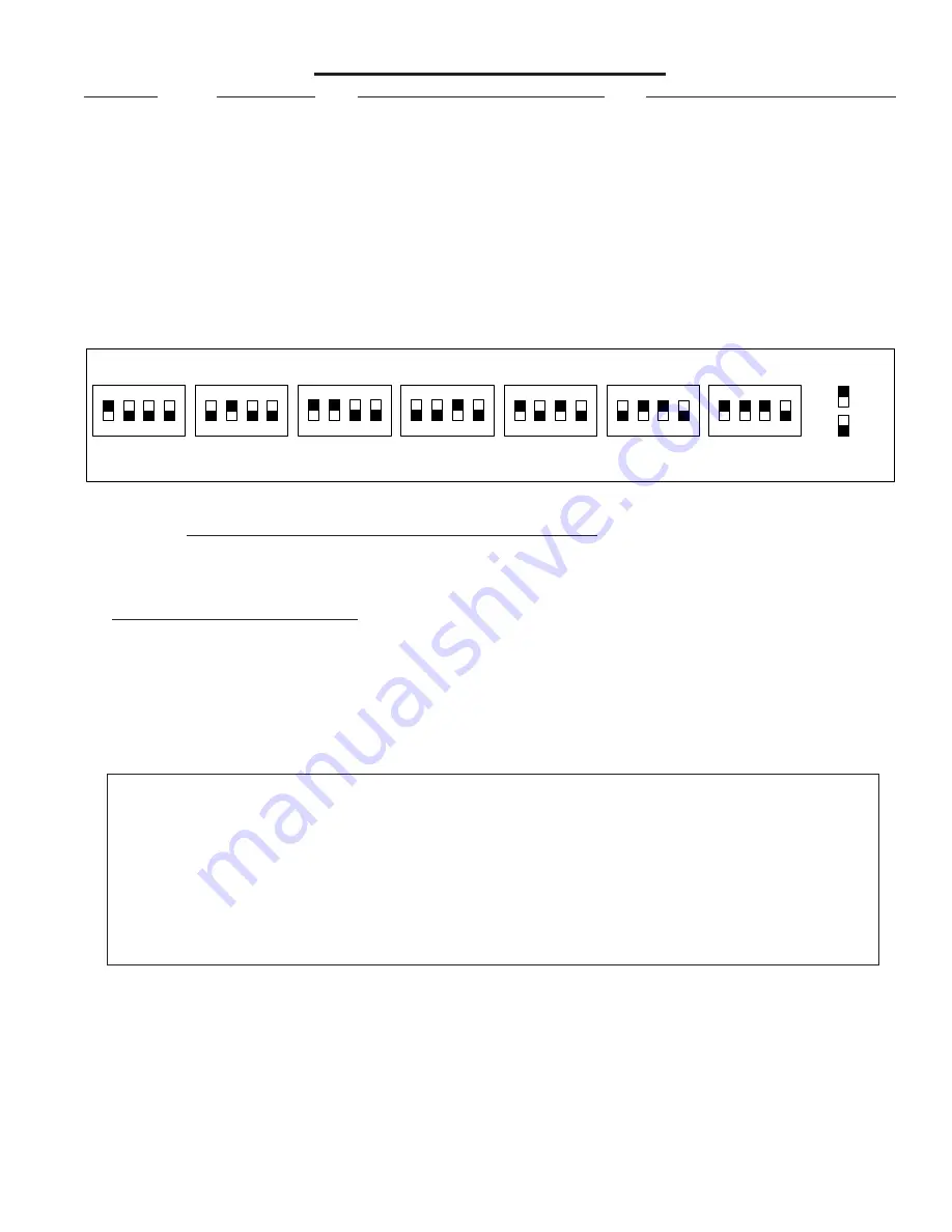
TABLE 1: Data Bus Address Switch Settings
ON
1
2
3
4
ON
1
2
3
4
ON
1
2
3
4
ON
1
2
3
4
Address
1
ON
1
2
3
4
ON
1
2
3
4
ON
1
2
3
4
Address
2
Address
3
Address
4
Address
5
Address
6
Address
7
LEGEND
ON
OFF
Data Bus Terminating Jumper JP1 –
This is engages a 120 Ohm resistor for terminating the M1 RS-485 Data Bus. See Data bus wiring instructions before use.
For
Data
Bus
Type
5
Devices
(Serial
Expanders)
the
only
valid
Addresses
are
1
thru
7
and
therefore
the
maximum
number
of
Type
5
Devices
is
7.
Mounting - Connections - Setting the Data Bus Address - Enrolling the Data Bus Device
1. Turn off the M1 Master Power Switch and unplug the Leviton VRC0P-1LW (vizia rf+3) before making any wiring connections.
2. Mount the M1XSLZW as close as possible to the Leviton VRC0P-1LW (vizia rf+3) . The RS232 Serial cord supplied by
Leviton is approximately 8 ft. DO NOT use an extension or attempt to make this cord any longer!
3. Follow the wiring recommendations in the M1 Installation Manual to connect the data bus ter12V, A, B, and Neg from
the M1 Control to the terminals on the M1XSLZW.
It may be necessary to install an M1DBH or M1DBHR Data Bus Hub if
more than 2 homerun data bus cables are coming into the M1 Control.
4. Set the data bus address switches on the M1XSLZW to a value between 1 and 7 following the diagram below. Make sure the
address you select is NOT being used by any other data bus Type 5 (serial expander) device. Each switch has an OFF and
On position (binary value 0 or 1). The combination of these switches represents a decimal value of between 0 (all Off) and 15
(all On).
5. Connect the Leviton VRC0P+3 Serial Interface to the M1XSLZW using the modular RS232 serial cable supplied with the
VRC0P+3.
DO NOT use an extension or attempt to make this cord any longer!
6. Once all wire connections are complete plug the Leviton VRC0P+3 into a convenient AC Output that is NOT controlled by a
switch (Always On 24hours). Next, turn on the M1 Master Power Switch which will then supply power to the M1XSLZW.
7. Enroll the M1XSLZW to the M1 Control.
REQUIRED! This is done either via a Keypad or ElkRP Software. From a Keypad
access the Installer level programming and select Menu 01-Bus Module Enrollment. Press the right arrow key to start the
enrollment. When complete press the right arrow (edit) key to view the results. The M1XSLZW shares the same bus type as
other serial expanders and will display as a "SerialPExpdr T5" followed by a specific address (Addr) number. Verify that the
address displayed matches the address selected in step 4 above.
Should it become necessary to replace a M1XSLZW then set the replacement unit to the same address as the old unit
and perform the enrollment process. To permanently remove any data bus device perform the enrollment process AFTER
disconnecting the device. This will help avoid a "missing device" trouble condition.
STEP 2 - Setting up the M1XSLZW
* * IMPORTANT - PLEASE READ * *
1) Elk does not recommend mixing (combining) Z-Wave devices with other lighting technologies (e.g. Insteon, UPB,
Zigbee, Lutron, etc.) on any installation. Potential interference, device ID overlap, and other issues can lead to unreliable
operation. If mixing of technologies cannot be avoided, the Installer must assume all risk and liability. Elk does not
endorse or support the mixing of Z-Wave and other lighting technologies.
2) Z-Wave Thermostats CANNOT BE MIXED (combined) with other Thermostat technologies or brands. I.E. Do not
mix hardwired Thermostats such as RCS RS485, HAI RS232, or Aprilaire RS485 on the same M1 panel with Z-Wave
Thermostats. If this advice is not followed AND Z-Wave Thermostats become mixed with hardwired Thermostats on the
same installation NO DATA will be displayed for the Z-Wave Thermostat(s).
TABLE 2: Diagnostic LED Indicator
Slow blink
(1/2 sec.) = Normal communication with M1.
Rapid flicker
= Discovery Mode. The M1XSLZW is synchronizing with the VRC0P+3 to collect all current
data. This is automatically performed upon reboot or power up.
No blink
= No communication with M1. Check the wiring with the M1 and that the device has power.


