M1XSLZW Instruction Manual
Page 12
TEXT String
<LOCK1^M
<LOCK2^M
<LOCK3^M
<LOCK4^M
<LOCK5^M
<LOCK6^M
<LOCK7^M
<LOCK8^M
<LOCK9^M
<LOCK10^M
Command interpretation
Lock Z-Wave Lock Node ID mapped to LOCK1
Lock Z-Wave Lock Node ID mapped to LOCK2
Lock Z-Wave Lock Node ID mapped to LOCK3
Lock Z-Wave Lock Node ID mapped to LOCK4
Lock Z-Wave Lock Node ID mapped to LOCK5
Lock Z-Wave Lock Node ID mapped to LOCK6
Lock Z-Wave Lock Node ID mapped to LOCK7
Lock Z-Wave Lock Node ID mapped to LOCK8
Lock Z-Wave Lock Node ID mapped to LOCK9
Lock Z-Wave Lock Node ID mapped to LOCK10
TABLE 6: Z‐Wave Lock Commands from M1 TEXT Strings
TEXT String
<ULOCK1^M
<ULOCK2^M
<ULOCK3^M
<ULOCK4^M
<ULOCK5^M
<ULOCK6^M
<ULOCK7^M
<ULOCK8^M
<ULOCK9^M
<ULOCK10^M
Command Interpretation
UnLock Z-Wave Lock Node ID mapped to LOCK1
UnLock Z-Wave Lock Node ID mapped to LOCK2
UnLock Z-Wave Lock Node ID mapped to LOCK3
UnLock Z-Wave Lock Node ID mapped to LOCK4
UnLock Z-Wave Lock Node ID mapped to LOCK5
UnLock Z-Wave Lock Node ID mapped to LOCK6
UnLock Z-Wave Lock Node ID mapped to LOCK7
UnLock Z-Wave Lock Node ID mapped to LOCK8
UnLock Z-Wave Lock Node ID mapped to LOCK9
UnLock Z-Wave Lock Node ID mapped to LOCK10
Gets the current status of a Z-Wave Lock. Substitute the Node ID (1–10) for x.
Useful for activating the Discovery Mode from a Rule
Sends a Battery Check (self-test) to a Lock. Substitute the Node ID (1–10) for x. Requires M1XSLZW firmware 81.0.4 or higher
Received by a rule indicating Good Battery (above 30%) Substitute the Node ID (1–10) for x. M1XSLZW firmware 81.0.4 or higher
Received by a rule indicating Low Battery (below 30%) Substitute the Node ID (1–10) for x. M1XSLZW firmware 81.0.4 or higher
Received by a rule indicating Lock Malfunction. Substitute the Node ID (1–10) for x. M1XSLZW firmware 81.0.4 or higher
<GSLOCKx^M
<POLL^M
<BCLOCKx^M
<GBLOCKx^M
<LBLOCKx^M
<JAMx^M
Each Z-Wave Lock in a network must have a unique Node ID from a pool of 128 Node IDs allowed. Up to ten (10) Z-Wave Locks
may be controlled by an M1. Special procedures and steps are required, including: 1) Mapping the Node ID of each Lock to one
of ten (10)
Virtual
lock numbers (
LOCK1-LOCK10
). 2) Creating M1
Text
Strings as Z-Wave Lock commands to the M1XSLZW.
3) Creating a "THEN Send Text to Port X" command in an ElkRP Rule. The
Text
will be your command and the
Port
X will be the
Data Bus Address of the M1XSLZW.
Mapping of the locks is done by the M1XSLZW on power-up using "Discovery Mode". This starts with the lowest Z-Wave Node
ID and searches UP until a lock is found. The first Lock found is mapped as LOCK1. If other Locks are found then the next higher
Node ID will be mapped to LOCK2, and so on. Discovery can only work after ALL Z-Wave devices (especially Locks) have been
setup, Associated, and Updated. See ElkRP instructions below:
6.1
Setup the Z-Wave network FIRST. (Page 3) All Z-Wave devices and controllers MUST be Associated and Updated.
At least 1 Lock and the VRC0P+3 must be installed.
6.2
Make a list of each Z-Wave device, its Node ID, location, and type (light, lock, thermostat, controller, etc.)
6.3
Verify that the M1XSLZW is connected to the VRC0P-1LW (vizia rf+3).
6.4
Power-up the M1XSLZW to start the Discovery Mode. This requires several minutes during which the status LED will flash
rapidly. DO NOT TOUCH anything until the rapid flashing changes to a slow 1 sec. flash
. As the M1XSLZW discovers a
Lock it will map it to one of ten (10)
Virtual
Lock numbers (
LOCK1-LOCK10
) and store them in memory, starting with the
lowest Node ID and working up.
6.5
Use the list of Z-Wave devices and select the first Lock (the Lock with the lowest Node ID).
6.6
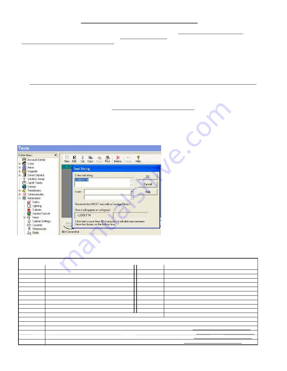
Select
ElkRP > Automation > Texts
and then Click on
New
to add a new Text String.
6.7
In the
Text String
field enter:
<LOCK1^M
{must be exactly as shown with the < and all capital letters}
6.8
Click
OK
to finalize this Text String. Your screen should resemble the illustration below:
STEP 6 - Adding Z-Wave Locks to
M1
Example: Text String "
<LOCK1^M
" is the com-
mand to lock the first Z-Wave Lock (LOCK1).
See Table 6 for additional Text Strings that may
be sent to control locks.
NOTE:
The only way to lock or unlock multiple
locks is to use multiple ElkRP Rules because a
ElkRP Rule cannot have multiple "THEN Send
Text to Port X" commands. Be aware that it can
take 8-10 seconds for a lock to respond. In the
case of multiple locks, each being controlled by
its own individual rule, it will require a significant
amount of time for all to complete.
IMPORTANT: A Lock command MUST be in its own separate ElkRP Rule. I.E. Any Rule that contains a THEN Send Text
through Port X command for controlling a lock MUST NOT contain any other THEN commands.


