


M1XSP Installation Manual
Page 5
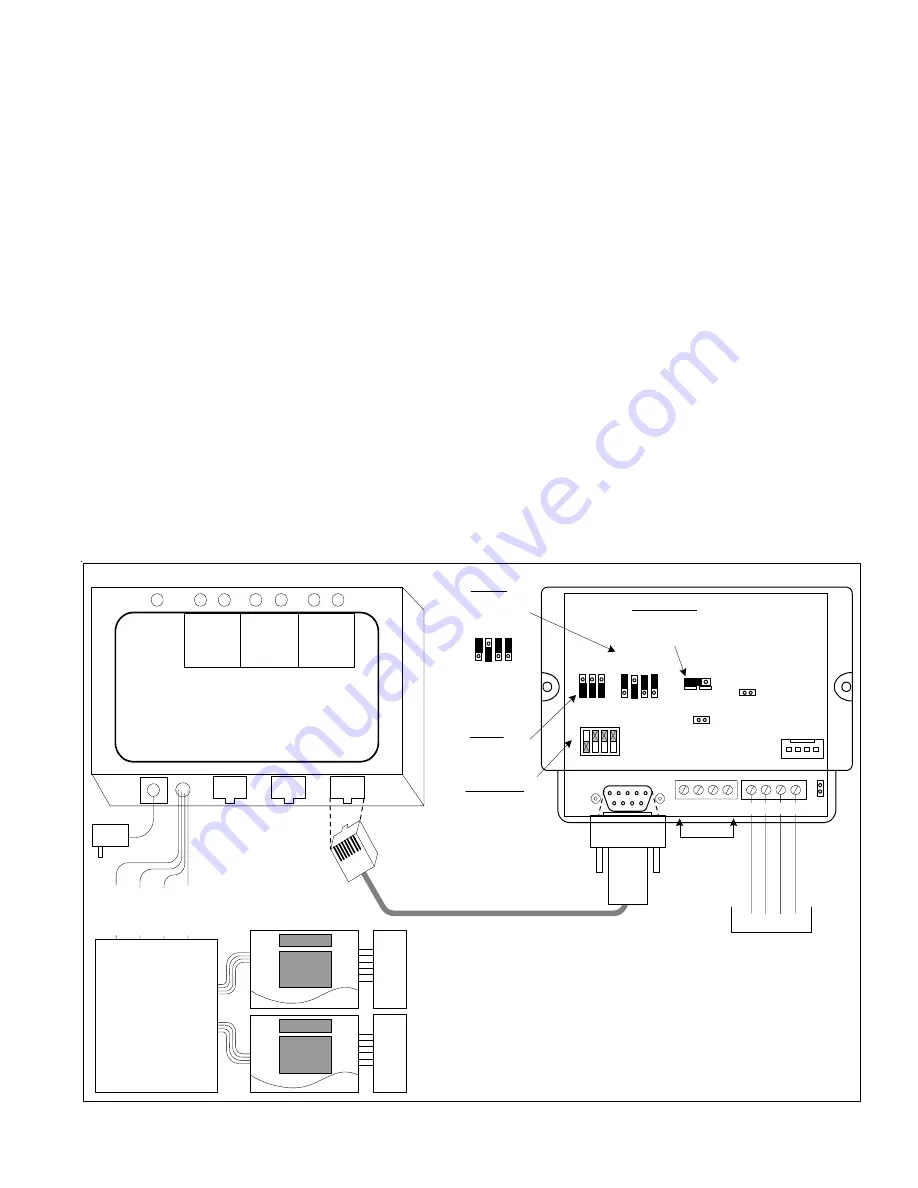
POWER
Aprilaire
Electronic Thermostat
Model 8811 Protocol Adapter
Power
7.5VAC RS-485 RS-485 RS-232
C
LEDs
RX TX
DATA
RS-485
RX TX
ENABLE
RS-485
RX TX
DATA
RS-232
B
A
RS-485
Not Used
BL
/W
T
The thermostat brand, interface format, and model of ELK-M1
Control dictates the total number of thermostats allowed.
The ELK-M1G can interface with up to 16 Aprilaire 8870
Thermostats total using 1 M1XSP.
The ELK-M1 (Std) can only interface with 2 Aprilaire 8870 Thermostats.
+VKP A B Neg
To M1 Control
Data Bus Terminals
ADDRESS
Switch 1 shown in ON
position (Address 1).
Switches 2,4,8 are Off.
MODE
For Aprilaire
set to 1011 **
Place plug on top
pins for a 1, on
bottom for a 0.
BAUD
No changes
needed.
OR
/W
T
BK/
W
T
RD/
WT
Aprilaire 8818
DISTRIBUTION
PANEL
One required per
eight (8) thermostats
Aprilaire 8870
THERMOSTATS
HVA
C
SYSTEM
H
VAC
S
YSTEM
Address
1 2 4 8
ELK-M1XSP
Interface
1
0
1 2 3 4
RS-232
ON
232 485
JP1
JP2
JP3
+12V A B Neg
JP5
Jumper JP3
must be in 232
position.
6 ft. Cable with RJ and DB9 connector
shipped with Aprilaire 8811.
BAUD MODE
1
0
S1 S2 S3
S5 S6 S7 S8
** Early production units do not have the S5 Jumper
S5 S6 S7 S8
1.
Install and wire the Aprilaire 8811 Protocol Adapter, 8818 Distribution Panel (optional), and the 8870 Thermostat using
instructions from Aprilaire.
2.
Install the ELK-M1XSP per the instructions on page 3. Be sure to enroll the device into the M1.
3.
Set the MODE jumpers S5=
1
, S6=
0
, S7=
1
, & S8=
1
for Aprilaire. If the M1XSP has a jumper S4, set it to =
1
. Set Jumper
JP3 to the "
232
" position. The BAUD jumpers S1,S2, & S3 do not matter as the Aprilaire baud rate is preset internally.
4.
Plug the Aprilaire supplied 6 ft RJ to DB9 Cable between the 8811 Protocol Adapter and the ELK-M1XSP. DO NOT USE
THE ELK-WO37A CABLE.
5.
Power up the Aprilaire Thermostat and Protocol Adapter.
6.
Program the unit address and any other options in the Thermostat per its instructions. The unit address must match the
Thermostat number in the M1 Control. The first Thermostat should be Address 1.
7.
Using the ELK-RP Software, program the M1 using steps A,B, and C. Test and verify operation using steps D and E.
7a. Click on the Automation Tab in the ELK-RP software. Click on Thermostat icon and program a name for Thermostat 1.
7b. Click on the Task icon and program at least two tasks. Name the 1st Task "Economy Mode" and the 2nd "Comfort Mode".
7c. Click on the Rules icon and create the following 4 rules.
Whenever [Area Name] Armed State Becomes Armed Away
Whenever [Task Name] (Task 1) Is Activated
Then Activate [Economy Mode] (Task 1)
Then Set [Thermostat 1] (TStat 1) Cooling Desired Temp to 85 degrees
Whenever [Area] Armed State Becomes Disarmed
Whenever [Task Name] (Task 2) Is Activated
Then Activate [Comfort Mode] (Task 2)
Then Set [Thermostat 1] (TStat 1) Cooling Desired Temp to 70 degrees
7d. Use the M1 Keypad to verify the M1XSP & Thermostat operation. Press the ELK key followed by the Right arrow key to
access Menu 1-View/Control Automation Fncts. Press 6 for the Thermostat Temperature sub-menu, followed by Right
arrow key. The Keypad should display the first Thermostat (T01) along with its name and current temperature reading.
7e. Go into the Tasks sub-menu and select Economy Mode (Task 1). Press the # key to activate. When this task is activated
the thermostat cooling setpoint should go to 85 degrees. Confirm this on the display.
Aprilaire 8870 Thermostat


