ELK-M1XRF319 Installation Manual
Page 5
LED Display
8
4
2
1
‐
‐
‐
‐
‐
‐
‐
‐
‐
‐
‐
‐
‐
‐
‐
‐
‐
‐
‐
‐
Data Bus
Address
2
3
4
5
6
7
8
9
10
11
12
13
14
15
Suggested Wireless
"Starting Point"
Zone 17
Zone 33
Zone 49
Zone 65
Zone 81
Zone 97
Zone 113
Zone 129
Zone 145
not valid
not valid
not valid
not valid
not valid
Switch Settings
S1
S2
S3
S4
Off
On
Off Off
On On
Off Off
Off Off
On
Off
On
Off
On
Off
Off
On On
Off
On On On
Off
Off Off Off
On
On
Off Off
On
Off
On
Off
On
On On
Off
On
Off Off
On On
On
Off
On On
‐
‐
‐
‐
‐
‐
‐
‐
Data Bus
Address
2
3
4
5
6
7
8
9
10
11
12
13
14
15
Starting and Ending
Zone Numbers
Zones 17 ‐ 32
Zones 33 ‐ 48
Zones 49 ‐ 64
Zones 65 ‐ 80
Zones 81 ‐ 96
Zones 97 ‐ 112
Zones 113 ‐ 128
Zones 129 ‐ 144
Zones 145 ‐ 160
Zones 161 ‐ 176
Zones 177 ‐ 192
Zones 193 ‐ 208
not valid
not valid
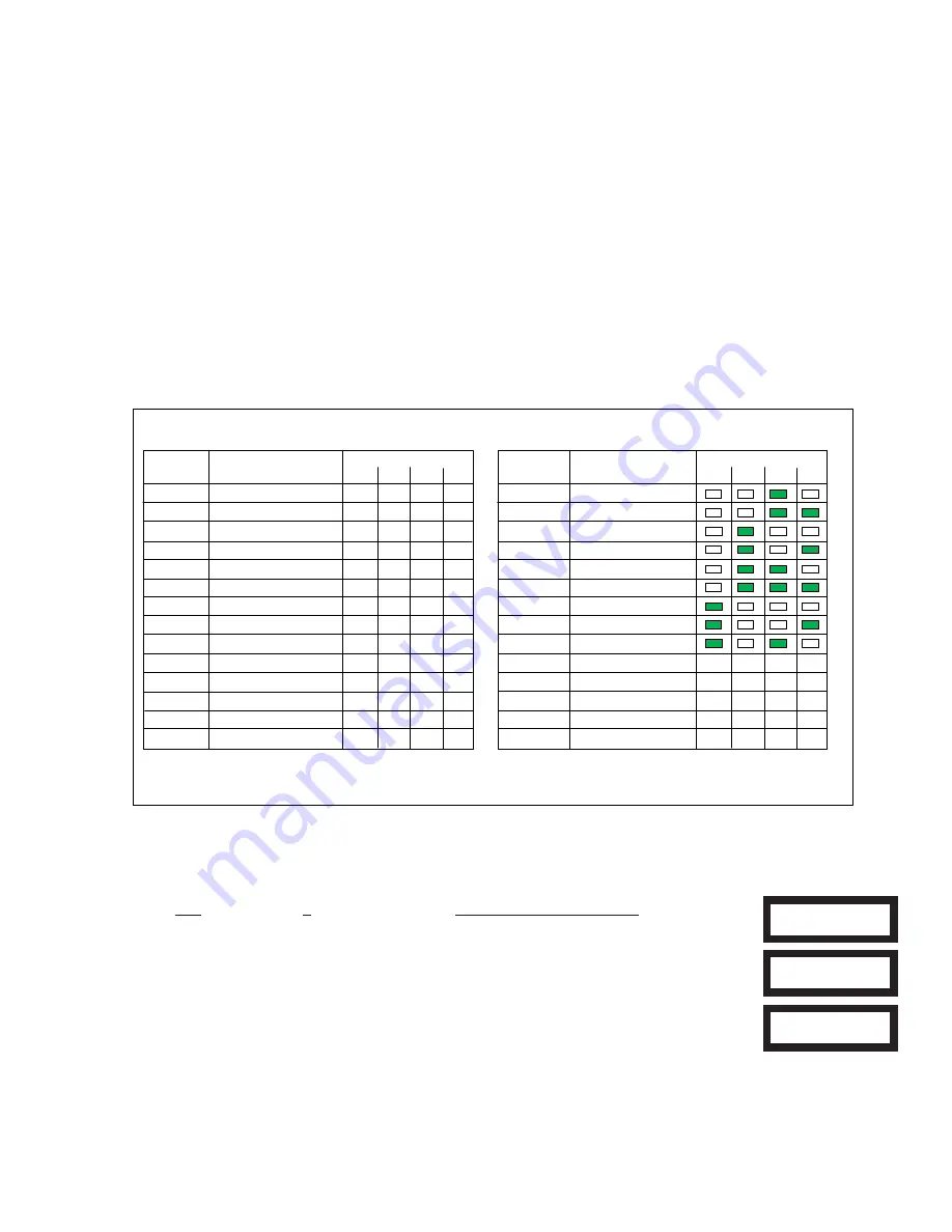
Table 1‐1
Table 1‐2
Wireless Receiver Expanders (M1XRF319)
Hardwired Zone Expanders (M1XIN)
Data Bus Enrollment:
:
Once the address is set and the Wireless Receiver is powered up it must be manually ENROLLED with the M1 Control. This can
be performed from keypad programming "Menu 1 - Bus Module Enrollment" or ElkRP Remote Programming Software.
(The steps below require an M1 LCD Keypad)
1. Press the
ELK key, then press 9 (or scroll up) to display
9 - Installation Programming.
Press the
RIGHT arrow key to select this menu. The Installer Program Code (PIN) must be entered to access
this menu.
2. Enter the Installer Program Code. (The default code is 172839)
3. The first Installer Programming menu displayed will be "Bus Module Enrollment"
4. Press the RIGHT arrow key to select this menu. "Enrolling Bus Modules" will display
5. The control will transmit an enrollment message to all data bus devices, followed by a display
showing the total Bus Modules that are enrolled. To view the enrolled devices and/or remove a
device press the RIGHT arrow key next to the word Edit.
6. Press the * or Exit keys to exit Installer Programming.
XX Bus Modules
Enrolled, Edit
r
Auth. Required
Enter Valid Pin
01-Bus Module
Enrollment
Examples of Data Bus Address Settings
Conflicts can exist if a group of hardwired zones are allowed to overlap or intrude where wireless sensors/zones exist.
Wireless
sensors/zones and hardwired zones MUST NEVER be allowed to overlap!
If there is a likelihood of future wireless zone expansion
then we recommend skipping up to a higher address to install a hardwired expanders. This effectively leaves open addresses for
future wireless. Do NOT install any Hardwired Expanders in that open address space. Tables 1-1 and 1-2 illustrate the Data Bus
Address setting of a wireless receiver while pointing out Addresses to avoid when adding or installing Hardwired Expanders.
- Never assign a Wireless Receiver and a Hardwire Expander to the same Data Bus Address.
- Never assign a Hardwire Expander to any Address that correlates to Wireless Transmitter/Zones. EG: If a Control has 40
wireless transmitters/zones and the Receiver is set to Address 2 the first wireless zone will be 17 and the last will be 57.
Referring to Table 1-1 we see that zone 57 correlates to Data Bus Address 4. In this example a hardwired expander CANNOT
be installed at Addresses 2, 3, or 4 since those addresses correspond to Zones 17 to 64.
- Never learn a new wireless transmitter that spills over into a data bus address assigned to a Hardwired Expander.
- Try to always keep wireless transmitter zones so they are contiguous and never split up by any hardwired expanded zones.
Data Bus Addresses whose zone IDs are effectively "overlapped" by wireless zones are considered "reserved" for wireless use
and should not be used by a hardwired zone expander. See Appendix C.
- The maximum number of wireless zones is 144 and the last wireless zone number cannot be greater than 160.
NOTE: Consider whether the system may ever need additional wireless or hardwired zones. If the answer is yes, we
suggest the data bus address assignments be strategically set to permit future growth without being forced to re-arrange
the addresses at a future date or defaulting the control and starting over.


