Elimko
E-PR-200
KY-PR200-0420-0
PAGE
44/56
the parameter
Set Source
.
Min. Set :
Minimum configurable internal set value.
Max. Set :
Maximum configurable internal set value.
Min. Out :
Minimum output value in %percentage. When the calculated output value is less than the
minimum output value, the output value is set to minimum output value.
Max. Out :
Maximum output value in %percentage. When the calculated output value is more than
the maximum output value, the output value is set to maximum output value.
Cycle Time :
Cycle time determines the PID PWM ouput period and is only applied to the digital
outputs and is entered in seconds. Short values of cycle times result more precisional and
accurate contol but may cause the control element (actuator) wear faster than would be
with long cycle times.
Control Form :
Determines the control form of PID output. REVERSE output form makes the control
output increase when the error signal (Process Value – Set) increases, conversely
FORWARD selection makes the control output decreases when the error signal increases.
When deciding the control form of PID Loop, how the control output will affect the
process variable should be in mind. For instance cooling outputs causes a reverse reaction
of temperature output.
Proportional
Band
:
Proportional band of PID loop in engineering unit.
Integral Time :
PID loop integral time in seconds. 0 value of integral time disables integration.
Derivative Time :
PID loop derivative time in seconds. 0 value of derivative time disables derivation.
Set Source :
Please see
Set Type
parameter.
Manual Reset :
Output value corresponding to zero error signal(PV-Set). %50 is recommended if there is
no priory information.
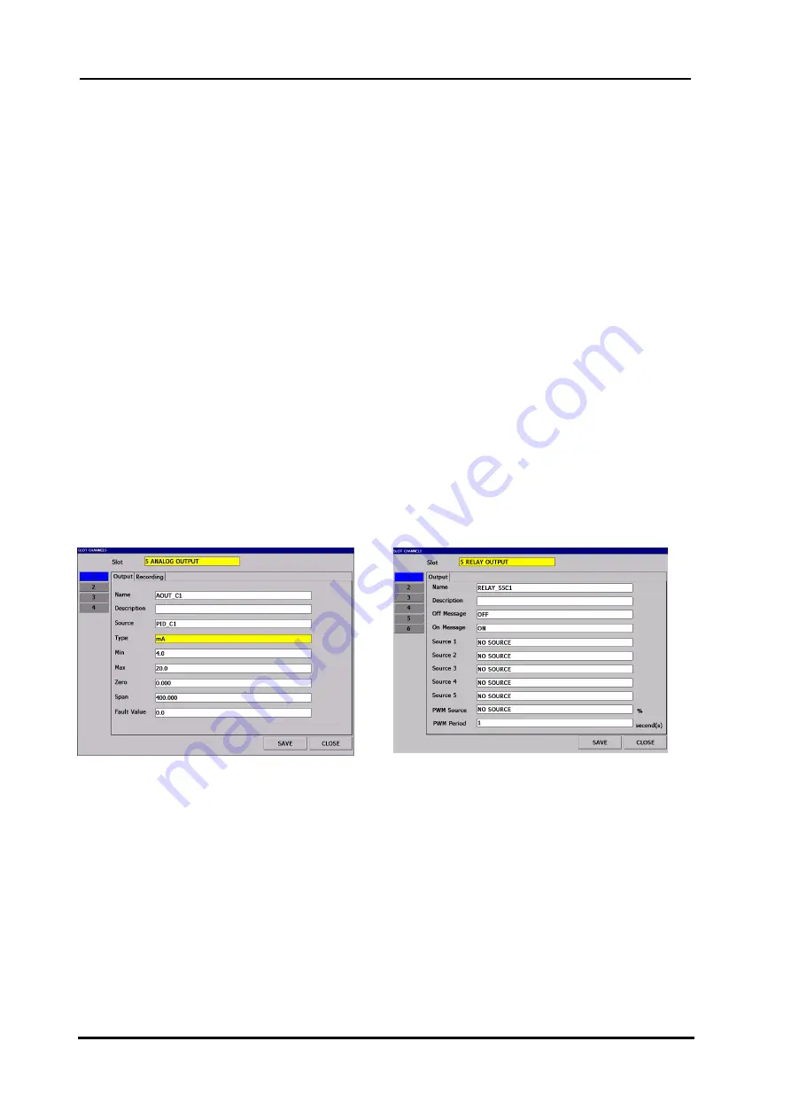
PID Sources can be directed to analog output, relay or digital output channels. When the analog outputs are used
for control signal, Zero and Span parameter of the analog output should be assigned 0 and 100 respectively. When
the digital output sources are used for control signal, PWM sources of the digital sources should be assigned to the
PID source to be directed.
Figure 6.72 Definition of PID Source to Analog Output
Figure 6.73 Definition of PID Source to Relay Output
When the fisrt group channel of an group is assigned to a PID source, usual Trend View appears different and
turns to PID control page form which provides a clear display of PID process variables and enables user to enter
manual set and control output. Please see
Figure 6.74
and
6.75
.
Содержание E-PR-200 Series
Страница 47: ...Elimko E PR 200 KY PR200 0420 0 PAGE 47 56...
Страница 55: ...Elimko E PR 200 KY PR200 0420 0 PAGE 55 56...


