15P0056B1
APPLICATION MANUAL
AMS90/1
12/17
TERMINAL BOARD DESCRIPTION
TERMINAL BOARD DESCRIPTION
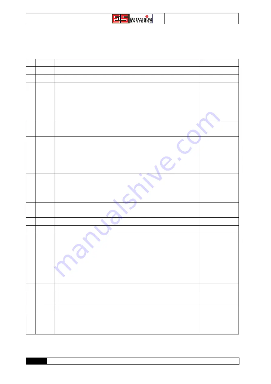
SIGNAL TERMINAL BOARD
SIGNAL TERMINAL BOARD
1
0V
0V
2
TG
Input for tacho generator feedback
R
in
≈
107k
Ω
3
0V
0V
4
D IN
Input for direct reference 0…+10V
CC
R
in
≈
10k
Ω
7
R IN
With
J4
in pos.
V
:
ramp input for voltage signal 0…+10V
DC
.
With
J4
in pos.
I
:
direct input for current signal 4…20mA.
J4
⇒
V
:
R
in
≈
107k
Ω
J4
⇒
I
:
R
in
≈
107k
Ω
8
R OUT
Ramp circuit output 0…+10V
DC
+10V
DC
max
(6mA max)
9
I LIM
With
J5
in pos.
I
:
terminal not connected.
With
J5
in pos.
E
:
input for external setting of current limit 0…-10V
DC
.
A reference of -10V
DC
can be used to set the AMS90/1 rated current.
R
in
= 10k
Ω
11
n OUT
Speed signal output (voltage) for tacho (voltmeter) or for cascade
reference distribution.
Adjustable through trimmer RV6 up to 10V
DC
.
STANDARD calibration: +10V
DC
at max. speed.
+10V
DC
max
(6mA max)
12
I OUT
Current signal output for possible ammeter.
STANDARD calibration: +10V
DC
at drive rated current.
+10V
DC
max
(6mA max)
13
+10V
CC
Supply output for +10V
DC
reference.
(6mA max)
14
-10V
CC
Supply output for -10V
CC
reference.
(6mA max)
18
RUN
With
J3
in pos.
L
:
the drive is operated if term. 18 is connected to 0V
(through insulated relay contact or NPN transistor output).
With
J3
in pos.
H
:
the drive is operated if term. 18 is connected to a positive voltage
10…30V
DC
(through insulated relay contact or NPN transistor
output).
J3
⇒
L
:
12V
DC
/ 1.2mA
J3
⇒
H
:
0.5mA con 10V
DC
1.9mA con 30V
DC
19
0V
0V.
20
n MIN
Resistive limit switch on negative end (CCW) of speed potentiometer,
for min. reference.
R
in
max = 10k
Ω
31
nZ(C)
32
nZ(NO)
NO contact of inner relay signalling motor at zero speed.
The relay is energized at stopped motor, by closing contact at term. 31-
32.
The relay switching usually occurs at 2.1% of max. speed.
250V
AC
/ 1250VA
... cont.


