


-48-
CIRCUIT DESCRIPTION - DIGITAL SECTION
THE DATA SWITCHES
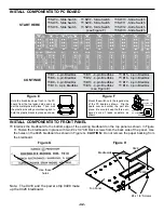
There are eight data switches labeled SW1 through SW8. The circuit is very simple. To perform the desired
functions, there is a double throw double pole switch, wired as a single pole double throw. One end is connected
to the 5V, the other to ground and the center lug is connected to the output.
THE LOGIC SWITCHES
The logic switches are also DPDT switches wired as SPST switches. The logic switches perform the same func-
tion as the data switches. That is, they produce high or low states. But there is one big difference. When switch-
ing the data switches, many pulses may be produced due to bouncing of the contacts.
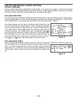
In the logic switches, only one pulse is produced at the IC output no mat-
ter haw many times the contacts bounce. This is extremely important if
you are producing pulses for counting circuits. Figure R shows the wiring
of the logic switch. The two NAND gates are connected so that when the
X input is grounded, the X output goes high. Opening and closing the
ground at X will not change the output. Only when X is grounded will the
output change to low. Thus, only one output change is produced with one
movement of the X switch. There are two outputs from each logic switch.
There are two outputs from each logic switch, X and X or Y and Y.
THE LOGIC INDICATORS
There are eight logic indicators. Figure S shows the circuit. It consists of a 74HC04 IC. When the input is over
2.8V, the output of the IC will be low, drawing current through the LED indi-
cator. The 120
Ω
resistor limits the current in the LED to less than 20mA.
When there is no connection to the input of the logic indicators, the two
100K
Ω
resistor bias the input to GND. This insures that the LED will be
off.
Figure R
Figure S
Содержание XK-550K
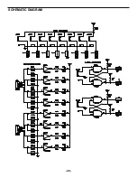
Страница 37: ...SCHEMATIC DIAGRAM ANALOG SECTION 36 ...
Страница 50: ...SCHEMATIC DIAGRAM 49 ...


