


MOUNT COMPONENTS TO PANEL
r
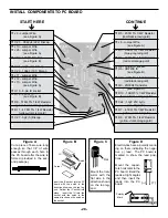
Push the illuminated switch into the hole in the top panel with the lugs as shown in Figure Q.
r
Install the fuse holder with the side lug in the position shown in Figure Q. Fasten the fuse holder in place
with the nut as shown in Figure R. Unscrew the cap and insert the fuse into the holder.
Side
Lug
Fuse Holder
Illuminated Switch
Nut
Top Panel
Plastic Washer
Fuse Holder
Back Side - Lower
Right Corner
Figure Q
Figure R
r
There is a raised area on the back side of the top panel. Screw the spacer to the raised area by inserting a
4-40 x 1/4” flat head screw into the hole in the raised area from the top side of the panel (see Figure S).
r
When mounting the bredboard, use the holes shown in Figure Ta. Mount the plastic spacer with a 4-40 x 1/4” flat
head screw as shown in Figure S. Next, mount the bredboard with two #4 x 1/4” AB black screws from the back
side of the top panel as shown in Figure S. The negative (blue) stripe should be on top and the numbers read-
ing from left to right should start with number 1 (see Figure Tb). CAUTION: Do not remove the paper backing
from the back of the bredboards. Do not over-tighten the black screws.
Spacer
4-40 x 1/4”
Flat Head
Screw
Top Panel
Bredboard
#4 x 1/4” AB Screws
Figure S
a
e
b
c
d
f
j
g
hi
1
5
10
ON
30VAC
+5
+12
--12
15VAC
OFF
15VAC
REGULATED
POWER SUPPLY
+ 2
0
C
D
--2
0
C
D
GND
Figure Tb
Figure Ta
-13-
Содержание XK-550K
Страница 37: ...SCHEMATIC DIAGRAM ANALOG SECTION 36 ...
Страница 50: ...SCHEMATIC DIAGRAM 49 ...


