


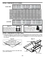


INSTALL COMPONENTS TO PC BOARD
INSTALL COMPONENTS TO FRONT PANEL
r
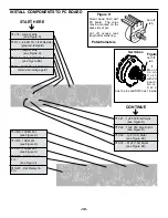
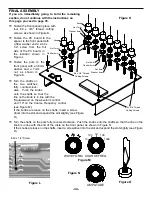
Interlock the bredboard to the bottom edge of the existing bredboard on the top panel as shown in Figure
H. Fasten the bredboards in place with two #4 x 1/4” AB black screws from the back side of the panel. Use
the holes on the 9426 bredboard as shown in Figure G. CAUTION: Do not remove the paper backing from
the bredboard.
9830
9426
Top Panel
Bredboards
#4 x 1/4” Screws
Use these
holes
Figure G
Figure H
-42-
START HERE
CONTINUE
Figure E
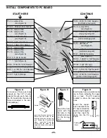
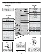
Hold the bredblox down flush to the PC
board from the top legend side and sol-
der the metal pins into place. Then, melt
the plastic pins with your soldering iron to
hold the plastic blocks in place as shown.
Figure F
Mount the switch onto the legend side
of the PC board as shown. Flip the
board over and solder the part into
place. Be sure to keep the three sol-
dered sets of leads separate as
shown.
Plastic Pins
Melted Pins
Switch
Legend side
of PC board
Foil side of
PC board
Solder
Note: The 9418 and the power strip 9408 make
up the 9426 bredboard.
r
SW4 - Slide Switch
r
SW7 - Slide Switch
r
SW10 - Slide Switch
r
SW5 - Slide Switch
r
SW8 - Slide Switch
r
SW11 - Slide Switch
r
SW6 - Slide Switch
r
SW9 - Slide Switch
r
SW12 - Slide Switch
(see Figure F)
r
SW13 - Slide Switch
r
B7 - 4-pin Bredblox
r
B11 - 4-pin Bredblox
r
B15 - 4-pin Bredblox
r
B8 - 4-pin Bredblox
r
B12 - 4-pin Bredblox
r
B16 - 4-pin Bredblox
r
B9 - 4-pin Bredblox
r
B13 - 4-pin Bredblox
r
B17 - 4-pin Bredblox
r
B10 - 4-pin Bredblox
r
B14 - 4-pin Bredblox
r
B18 - 4-pin Bredblox
(see Figure E)
Содержание XK-550K
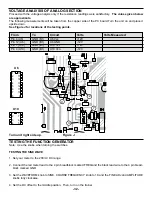
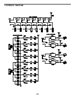
Страница 37: ...SCHEMATIC DIAGRAM ANALOG SECTION 36 ...
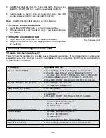
Страница 50: ...SCHEMATIC DIAGRAM 49 ...


