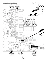


-30-
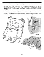
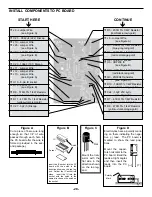
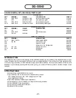
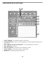
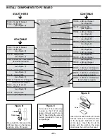
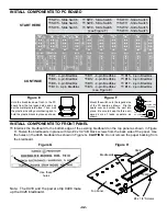
INSTALL COMPONENTS TO PC BOARD
START HERE
ê
Figure H
Mount down flush with
PC board.
The value
may be marked on the
back side of pot.
Cut off excess lead
length after soldering.
Potentiometers
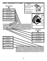
Switches
Figure
I
M o u n t
d o w n
f l u s h
with PC
b o a r d .
N o t e :
S W 2
has 12 pins and SW3 has 16 pins.
CONTINUE
ê
Cut off
tab
Cut off
tab
r
J18 - Jumper Wire
(see Figure A)
r
R13 - 8.2K
Ω
5% 1/4W Resistor
(gray-red-red-gold)
r
J17 - Jumper Wire
(see Figure A)
r
C18 - .001
µ
F (102) Mylar
(see Figure EA)
r
R6 - 12K
Ω
5% 1/4W Resistor
(brown-red-orange-gold)
r
VR6 - 100K
Ω
Pot
(see Figure H)
r
VR5 - 10K
Ω
Pot
(see Figure H)
r
VR7 - 100K
Ω
Pot
(see Figure H)
r
SW2 - SW Rotary 12
Pin
(see Figure I)
r
SW3 - SW Rotary 16
Pin
r
C21 - 1
µ
F 50V Electrolytic
(see Figure D)
r
C22 - 10
µ
F 25V Electrolytic
(see Figure D)
r
C20 - .1
µ
F (104) Mylar
(see Figure EA)
r
C19 - .01
µ
F (103) Mylar
(see Figure EA)
Содержание XK-550K
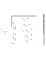
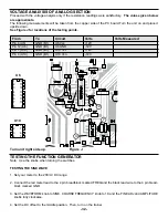
Страница 37: ...SCHEMATIC DIAGRAM ANALOG SECTION 36 ...
Страница 50: ...SCHEMATIC DIAGRAM 49 ...


