background image

8

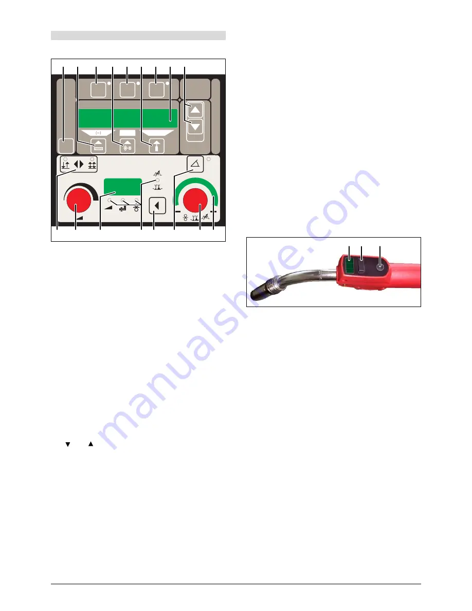
DP 20 operating panel

 43

“Mode” push-button


For switching between the operation modes Normal, 
Pulse, TwinPulse and Electrode.

 44

“Material” push-button


For selection of the material to be welded. The push-but-
ton is also used for the “Decrementing” (-) function, e. g., 
to reduce the value of a secondary parameter.

 45

“TT Save” push-button (Tiptronic)


For storage of a job.

 46

“Welding wire diameter” push-button


For diameter selection of the wire to be welded. The 
push-button is also used for the “End” function, with 
which you can switch back to the display of the previous 
menu level.

 47

“TT Enter” push-button (Tiptronic)


For acknowledgement when saving a job.

 48

“Gas type” push-button


For selection of the gas to be used. The push-button is 
also used for the “increment” (+) function, e. g., to in-
crease the value of a secondary parameter.

 49

“Tiptronic” push-button


For switching the Tiptronic mode on or off.

 50

Multi-function display


For indication of all parameter values and messages.

 51

 and   push-buttons (Enter)


For switching between the individual secondary param-
eters. Pressing both push-buttons at the same time is 
used for acknowledgement (Enter).

 52

“2-stroke / 4-stroke” push-button


For switching between 2-stroke and 4-stroke operation 
mode. A lit LED indicates the currently selected operat-
ing mode.

 53

Rotary pulse encoder for welding current / material thick-
ness


The rotary pulse encoder is used for adjustment of the 
required welding current and material thickness. The ad-
justment range can be limited, depending on the select-
ed material-wire-gas combination.

 54

Digital multifunction display


For indication of the primary parameters such as welding 
current, material thickness (in mm), wire feed speed (in 
m/min) or arc length correction.

 55

“Primary parameter” LEDs


These show which primary parameter is currently indi-
cated in the multifunction display

 54

.

56

“Primary parameter” push-button


For switching between welding current, material thick-
ness, wire feed speed and arc length, as indicated in the 
digital multifunction display

 54

.

 57

“Downslope” push-button


Switches the downslope function on or off. A lit LED next 
to the push-button indicates that the downslope is on.

 58

“Arc length / wire speed correction” rotary pulse encoder


For correction of the arc length or wire speed (depend-
ent on setting menu extra “arc lenght control“). Up to +/- 
40  % of the characteristic value can be corrected.

 59

“Arc length / wire speed correction” LED indication


Indicates the degree of the correction. When the upper-
most center LED is lit, the programmed arc length/wire 
speed remains unchanged; “0” is indicated in the multi-
function display

 54

. Turn the rotary pulse encoder

 58

 left 

to reduce the arc length/wire speed; turn the rotary pulse 
encoder

 58

 right to enlarge the arc length/wire speed


.

 60

Torch display


Indicates the current welding power, material thickness, 
wire feed speed or arc length correction (identical with 
the digital multifunction display

 54

). In Tiptronic mode, 

the current job set and the current job number are indi-
cated.

 61

Torch rocker


For changing the welding power, material thickness or 
arc length (depending on which value is being indicated 
in the digital multifunction display

 54

).


In Tiptronic mode, the rocker can be used to switch be-
tween the active jobs or job sets.

 62

Torch “Modus” push-button


Has the same function as the “Primary parameter” push-
button

 56

 on the DP20 operation panel.


In Tiptronic mode this push-button can be used to switch 
between job selection and job-set selection.

Current / voltage display

The actual welding voltage and welding current values are in-

dicated during the welding. After the welding procedure, the 

“Hold” LED lights up and the last welding voltage and welding 

current values are indicated. When the operator changes cer-

tain welding adjustments (e. g. level, program, job), the “Hold” 

LED goes out and the reference values for current and volt-

age are indicated.

11 Setting into operation

TT

Save

Enter

Tiptronic

(END)

(+)

TT

Enter

Mode

mm

 43  44

 45  46  47  48  49  50  51

 52  53

 54

 55  56

 57

 58  59

 60

 62

 61

Содержание MULTIMIG 400puls

Страница 1: ...EN Fabrik für Elektrotechnik GmbH x Postfach 10 59 60 x D 28059 Bremen Telefon 49 0 421 54 90 6 0 x Telefax 49 0 421 54 90 619 x vertrieb elektron bremen de x www elektron bremen de Operation Manual MULTIMIG 400puls ...

Страница 2: ...2 5 5 6 10 8 9 6 7 12 15 14 11 10 ...

Страница 3: ...welding site Secure yourself and the unit at higher or inclinational plac es Connect the unit only at mains with correct connection to ground earth and at prolongations and sockets too Wear correct protective clothing gloves and leather apron Protect the welding area with curtains or mobile walls against rays Do not thaw frozen waterpipes or conductions with this unit In high electrical risk areas...

Страница 4: ...against disturbances If other devices are disturbed it may be necessary to pro tect additionally The affected area can be bigger than your premises property depends of the building etc Please use the unit conform to the instructions of the manu facturer The user is responsible for installation and use of the machine Furthermore the user is responsible to eliminate the disturbances caused by electr...

Страница 5: ...tton 48 gas type solenoid valve is activated and adjust gas amount on the pressure reducer rule of thumb wire diameter x 10 gas flow Keep the wire insert switch pressed until the welding wire protrudes approx 10 mm out of the gas nozzle on the torch neck Select welding material by pressing button 44 Select wire diameter by pressing button 46 Select shielding gas type by pressing button 48 Select 2...

Страница 6: ... should be corresponding to the technical data How to insert the wirespool Open the lid at the machine or at the wire feed case 2 and screw off the nut 26 from the wire coil pick up 24 Put on the wire coil at the wire coil pick up and pay attention that the tappet is well insert at the coil 23 By use of small wire coils please use the adapter Adjust the brake 25 by releasing the torch button the w...

Страница 7: ...eter 32 This should be approx wire diameter x 10 l min The content of the cylinder is shown by the contentmanometer 33 How to modify the machine for aluminium welding Change the wire roll to a aluminium wire roll Change the steel torch against an aluminiumtorch or resp change the wire liner against a teflon liner Remove the capillary tube 42 at the central connection Cut the teflon liner close to ...

Страница 8: ...rrent material thick ness wire feed speed and arc length as indicated in the digital multifunction display 54 57 Downslope push button Switches the downslope function on or off A lit LED next to the push button indicates that the downslope is on 58 Arc length wire speed correction rotary pulse encoder For correction of the arc length or wire speed depend ent on setting menu extra arc lenght contro...

Страница 9: ... the character with the pushbuttons 48 and 44 Extras 1Machine data Operating system Master Version number operating system Master Operating system Process Version number operating system process Operating system DMRs Version number motor assembly ies Welding program version Version number welding programs Operating hour counter Indication of the welding duration in h min sec Configuration Machine ...

Страница 10: ... to frequently recurring welding tasks or save the set tings which individual welders use specifically for their jobs Programming jobs Determine the optimal welding adjustment Press the TT Save button 45 Save LED flashes Select the target job number with the push buttons 44 and 48 or with the torch rocker and confirm with the TT Enter push button 47 if you do not press Enter the Save LED goes out ...

Страница 11: ...et job number Assigning job texts An individual text can be assigned to each job in order to spe cially mark it or allocate it more clearly Switch on the Tiptronic function with the Tiptronic push button 49 Select the job number with the push buttons 44 and 48 Press the and push buttons 51 at the same time a flashing cursor appears in the display 50 in order to get into the edit mode The cursor is...

Страница 12: ...w rate of water Check level of cooling liquid and coolant filter E06 Overvoltage Output voltage too high Notify service E07 EEProm checksum error Adjustment data faulty or not available Switch system off and then on again E08 Wire feed tacho Current input from feed motor too high No tacho signal available Blow out torch package with compressed air and check wire feed unit E09 Error v a measuring F...

Страница 13: ...r vertical down welding The transfer of the electrode to the workpiece takes place partly in short circuit and in free flight Due to less short circuiting the weld ing pool is hotter than at the short circuit arc Welding with transitional arc provides higher electrode melt rate and is more economic than welding at short circuit arc Long arc Long arcs are typical at welding at the higher ampere ran...

Страница 14: ...t is wide enough you should weld two parallel string beads At vertical up position the side to side motion should describe the shape of an open triangle Length of the arc Welding with a longer arc reduces the penetration the weld ing bead is wide and flat with increased spattering The weld ing material is transferred with slightly larger drops than at welding with a shorter arc A longer arc is use...

Страница 15: ...ssary wire feed speed vD results from the product of pulse frequency fP and the wire length l melted in each pulse period From this relationship you see that a change in wire feed speed re quires a linear change in pulse frequency A rise in electrode melt rate by increasing wire feed speed therefore needs a higher pulse frequency The objective drop diameter should be about 1 2 mm with a wire diame...

Страница 16: ... or wire welds to the con tact tip Wire electrode is tight at the spool Check and change if necessary Burr at the wire beginning Cut the wire beginning again Irregular wire feeding or no wire feeding Wrong contact pressure at the wire feed rolls Adjust it as described in the manual Torch defect Check and change if necessary No brass pipe in the central connection or is dirty Install or clean the b...

Страница 17: ...amp and workpiece Ground cable not right plugged in Fasten ground cable by turning the plug to the right Defect torch Repair or replace it Hot plug of ground cable Plug was not tightened by turning to the right Check Higher wire wear out at wire feeding unit Wire rolls does not fit to the wire diameter Install right wire rolls Wrong contact pressure at wire feeding Adjust as described at the manua...

Страница 18: ...18 ELEKTRON Bremen GmbH Postfach 10 59 60 D 28059 Bremen Germany Telefon 49 0 421 54 90 6 0 Telefax 49 0 421 54 90 6 19 Subject to change 18 Service ...

Страница 19: ...19 Appendix mounting torch holder ...

Страница 20: ...326601 06 05 ...

Отзывы: