background image

PS 8000 2U

640W - 3000W

32V - 720V

4A - 120A

PS 8032-20 2U: 

09 230 130 

PS 8080-120 2U: 

09 230 135

PS 8065-10 2U: 

09 230 131 

PS 8160-60 2U: 

09 230 136

PS 8160-05 2U: 

09 230 132 

PS 8360-15 2U: 

09 230 137

PS 8080-40 2U: 

09 230 133 

PS 8360-30 2U: 

09 230 138

PS 8080-60 2U: 

09 230 134 

PS 8720-15 2U: 

09 230 139

Laboratory Power Supply Series

Содержание PS 8000 2U Series

Страница 1: ...9 230 130 PS 8080 120 2U 09 230 135 PS 8065 10 2U 09 230 131 PS 8160 60 2U 09 230 136 PS 8160 05 2U 09 230 132 PS 8360 15 2U 09 230 137 PS 8080 40 2U 09 230 133 PS 8360 30 2U 09 230 138 PS 8080 60 2U 09 230 134 PS 8720 15 2U 09 230 139 Labornetzgeräteserie ...

Страница 2: ......

Страница 3: ... in dem dafür vorgesehenen Ein schub zu bestücken müssen die einschlägigen ESD Vorschrif ten beachtet werden Die Schnittstellenkarte darf nur im ausgeschalteten Zustand aus dem Einschub herausgenommen oder bestückt werden Eine Öffnung des Gerätes ist nicht erforderlich Allgemeines Impressum Bedienungsanleitung Labornetzgerät Serie PS 8000 2U Elektro Automatik GmbH Co KG Helmholtzstrasse 31 33 4174...

Страница 4: ...eige und Bedieneinheit 8 6 2 Tasten am Bedienfeld 9 6 3 Weitere Bedienelemente 11 6 4 Sollwerte einstellen 11 7 Verhalten bei 12 7 1 Einschalten mit dem Netzschalter 12 7 2 Ausschalten mit dem Netzschalter 12 7 3 Umschalten auf Fernsteuerung Remote 12 7 4 Überspannung 12 7 5 Übertemperatur 13 7 6 Spannungs Strom und Leistungsregelung 13 7 7 Fernfühlungsbetrieb 13 7 8 Netzüber Netzunterspannung 13 ...

Страница 5: ... Das Gerät ist mikroprozessorgesteuert dies erlaubt eine genaue und schnelle Messung und Anzeige von Istwerten Die Hauptfunktionen im Überblick Stellen von Strom und Spannung jeweils 0 100 Einstellbarer Überspannungsschutz 0 110 UNenn Einstellbare Leistung 0 100 Geräte ab 1kW Wechselbare Schnittstellenkarten CAN USB RS232 IEEE GPIB Analoge Schnittstelle für externe Ansteuerung und Mes sung mit 0 5...

Страница 6: ...nnungsschutz einstellbar 0 35 2V 0 71 5V 0 88V 0 88V 0 88V 0 176V 0 176V 0 396V 0 396V 0 792V Ausgang Strom Nennstrom I Nenn 20A 10A 40A 60A 120A 4A 60A 15A 30A 15A Einstellbereich 0 I Nenn 0 I Nenn 0 I Nenn 0 I Nenn 0 I Nenn 0 I Nenn 0 I Nenn 0 I Nenn 0 I Nenn 0 I Nenn Stabilität Netzausregelung 10 8 E 0 05 0 05 0 05 0 05 0 05 0 05 0 05 0 05 0 05 0 05 Stabilität bei 0 100 8 A 0 15 0 15 0 15 0 15 ...

Страница 7: ...ter 1 Fernfühlung positiv Sense B Lufteinlaßschlitze 2 Fernfühlung negativ Sense C Bedienfeld 3 Master Ausgang Strom D Analoge Schnittstelle 15polig weiblich 4 Master Ausgang Spannung E Slot für digitale Erweiterungskarten 5 Slave Eingang Strom F System Bus 6 Slave Eingang Spannung G Lüfter 7 Share Bus H Leistungsausgang M8 Schrauben 8 Masse J Netzsicherung Wert siehe Technische Daten K Netzbuchse...

Страница 8: ...n Der Querschnitt der Ausgangsleitungen richtet sich u A nach der Stromaufnahme der Leitungslänge und der Umgebungstem peratur Bei Lastzuleitungen bis 1 5m empfehlen wir bis 10A 0 75mm bis 15A 1 5mm bis 30A 4mm bis 40A 6mm bis 60A 16mm bis 120A 35mm pro Anschlußleitung Litze frei verlegt mindestens zu ver wenden Die Ausgänge und sind erdfrei so daß bei Bedarf einer von beiden geerdet werden kann A...

Страница 9: ...erden Die Taste kann durch den Zustand LOCK blockiert sein Siehe unten Über das Gerät Bild 3 In der Sollwertsatzauswahl Memory Select wird mit der Taste auch auf den zum Sollwertsatz gehörigen Spannungssollwert umgeschaltet aber der hier eingestellte Wert wird nicht sofort übernommen Die Anzeige sieht dann so aus Taste Preset UVL OVP Im Normalbetrieb dient die Taste zum Umschalten der Span nungsis...

Страница 10: ...endet den Preset Modus für rechts sofort oder er wird automatisch beendet wenn 5s lang keine andere Preset Taste gedrückt oder ein Sollwert verändert wird Im Fernsteuerbetrieb analoge oder digitale Schnittstelle kann hier der über die momentan benutzte Schnittstelle vorgegebene Sollwert kontrolliert werden Die Taste kann durch den Zustand LOCK blockiert sein Siehe unten In der Sollwertsatzauswahl ...

Страница 11: ...uittiert desweiteren Fehler Siehe Abschnitte 74 und 7 5 für Details Bedienung des Gerätes 6 3 Weitere Bedienelemente Tasten Drehgeber Die beiden Drehgeber haben eine Tastfunktion Durch Drücken einer oder beider Drehgebertasten kann folgendes ausgelöst werden a Feineinstellmodus Fine Ein kurzer Druck auf eine der beiden Tasten aktiviert bzw deaktiviert den Feineinstellmodus Fine Bei aktiviertem Fin...

Страница 12: ... dieAnschrift Gerätetyp und Firmwareversion an und ist danach betriebsbereit Im Setup siehe Abschnitt Geräte Se tup befindet sich eine Option Outp Rstr Output Restore die bestimmt wie der Zustand des Gerätes nach dem Einschalten ist Werksseitig ist diese aktiviert on Das bedeutet daß die Sollwerte U I P und der Zustand desAusganges ein oder aus wiederhergestellt werden so wie sie beim letzten Auss...

Страница 13: ...e der Strom steigen und die Spannung sinken Beispiel 2 Gerät ist in Strombegrenzung dieAusgangsspannung wird vom Widerstand des Verbrauchers bestimmt Nun wird die Leistung begrenzt also Leistungsregelbetrieb Damit sinken Ausgangsstrom und spannung auf die sich durch die Formel P U I ergebenden Werte Würde nun der Stromsoll wert weiter verringert so würde derAusgangsstrom weiter sinken und die Span...

Страница 14: ...RID Siehe CAN Terminologie für weitere Informationen Name Bus term Standardwert on Wertebereich on off Bedeutung Aktivierung Deaktivierung des Busabschlußwider standes bus termination der CAN Karte Der Abschluß ist erforderlich wenn die sich das Gerät am Ende des Busses befindet Folgender Parameter für RS232 Schnittstelle IF R1 Name Baud Standardwert 57600 Wertebereich 9600 19200 38400 57600 Bedeu...

Страница 15: ...en Spannungsbereich 0 30V IMax 1mA bei 5V Empfohlener Sender Open Collector gegen DGND 14 OVP DO Überspannungsfehler OVP HIGH UHigh 4V kein OVP LOW ULow 1V Quasi Open Collector mit Pull up gegen Vcc Bei 5V am Ausgang fließen max 1mA Imax 10mA bei Uce 0 3V Umax 0 30V Kurzschlussfest gegen DGND 15 CV DO Anzeige Spannungsre gelung aktiv CV LOW ULow 1V CC HIGH UHigh 4V Wenn Ausgang aus HIGH AI Analoge...

Страница 16: ...om und Spannung zus mit regelbarer Leistung Bedienung des Gerätes 11 Sonstiges 11 1 Ersatzableitstrommessung nach DIN VDE 0701 Die nach DIN VDE 0701 1 durchgeführte Ersatzableitstrom messung führt unter Umständen zu Ergebnissen die außerhalb der Norm liegen Grund die Messung wird in erster Linie an sogenannten Netzfiltern am Wechselspannungseingang der Geräte durchgeführt Diese Filter sind symmetr...

Страница 17: ...ammen vorgeben Dafür sind die getrennten Signale an den Pins 3 und 4 der Klemme System Bus vorgesehen Eine Beispielbeschaltung ist im Bild 5 zu finden Hier werden Spannung und Strom gleichzeitig vom Master vor gegeben Soll nur ein Sollwert von beiden vom Master bestimmt werden so sollte der andere Sollwert an den Slaves jeweils auf 100 gestellt werden Um das Gesamtsystem fernzusteuern reicht es da...

Страница 18: ...Klemme System Bus werden an allen Geräten parallel verbunden Wird Fernfühlungsbetrieb an der Last gewünscht so müssen je alle Sense und je alle Sense verbunden und an der Last ange schlossen werden Bild 6 Parallel Share Bus Betrieb Es wird empfohlen ein Gerät als Master festzulegen welches Gesamtstrom und spannung bestimmt Bei den Slaves sollten dann die Sollwerte für Strom Spannung und Leistung a...

Страница 19: ...hränkungen Über USB können von einem PC aus bis zu 30 Geräte angesteu ert werden entsprechende Hubs mit eigener Stromversorgung vorausgesetzt Die gilt prinzipiell auch für RS232 Unterschiede bestehen hier nur in der maximalen Kabellänge und Handha bung Für CAN gilt daß bis zu 30 unserer Geräte pro Adreßsegment mit anderen Busteilnehmern verbunden und durch Device Node und RID siehe Geräte Setup in...

Страница 20: ...20 2006 Elektro Automatik GmbH Co KG Irrtümer und Änderungen vorbehalten DE 2009 Elektro Automatik GmbH Co KG Irrtümer und Änderungen vorbehalten ...

Страница 21: ... 130 PS 8080 120 2U 09 230 135 PS 8065 10 2U 09 230 131 PS 8160 60 2U 09 230 136 PS 8160 05 2U 09 230 132 PS 8360 15 2U 09 230 137 PS 8080 40 2U 09 230 133 PS 8360 30 2U 09 230 138 PS 8080 60 2U 09 230 134 PS 8720 15 2U 09 230 139 Laboratory Power Supply Series ...
Страница 22: ......

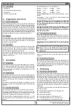
Страница 23: ...ces Date February 2009 Safety instructions Only operate the device at a mains voltage as stipulated on the type plate Never insert mechanical parts especially from metal through the air ventilation slots Avoid any use of liquids of any kind in the proximity of the device they might get into it Do not connect voltage sources to the device which are able to generate voltages higher than the nominal ...

Страница 24: ... Pushbuttons on the control panel 29 6 3 Further control elements 31 6 4 Adjusting set values 31 7 Behaviour of the device when 32 7 1 Switching on by power switch 32 7 2 Switching off by power switch 32 7 3 Switching to remote control 32 7 4 Overvoltage occurs 32 7 5 Overtemperature occurs 32 7 6 Voltage current and power are regulated 33 7 7 Remote sense is active 33 7 8 Mains undervoltage or ov...

Страница 25: ...d thus delivers fast and accurate measurement and indication of actual values The main functions at a glance Set voltage and current each with 0 100 Adjustable overvoltage threshold 0 110 UNom Adjustable power 0 100 models from 1kW Pluggable interface cards CAN USB RS232 IEEE GPIB Analogue interface for external control and monitoring with 0 5V or 0 10V selectable for 0 100 Powers of 640W 1000W 15...

Страница 26: ...V 0 71 5V 0 88V 0 88V 0 88V 0 176V 0 176V 0 396V 0 396V 0 792V Output Current Nominal current I Nom 20 10 40 60 120 4 60 15 30 15 Adjustable range 0A I Nom 0A I Nom 0A I Nom 0A I Nom 0A I Nom 0A I Nom 0A I Nom 0A I Nom 0A I Nom 0A I Nom Stability at mains fluctuation 10 8 I N 0 05 0 05 0 05 0 05 0 05 0 05 0 05 0 05 0 05 0 05 Stability at 0 100 8 OUT 0 15 0 15 0 15 0 15 0 15 0 15 0 15 0 15 0 15 0 1...

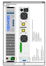
Страница 27: ...ilation slots 2 Sense C Control panel 3 Master output Current D Analogue interface 15pole female 4 Master output Voltage E Slot for digital extension cards 5 Slave input Current F System Bus 6 Slave input Voltage G Fans 7 Share Bus H Power output M8 screw block 8 Ground J Input fuse for value see Technical specifications K Power input socket 3pole IEC 60320 Figure 2 Rear side ...

Страница 28: ...perature Up to 1 5m lead length we recommend to use up to 10A 0 75mm up to 15A 1 5mm up to 30A 4mm up to 40A 6mm up to 60A 16mm up to 120A 35mm per cable flexible wire The outputs and are not grounded so that one of them may be grounded if necessary Attention When grounding one of the output poles always check if one of the poles of the load eg electronic load is also grounded This could result in...

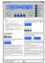
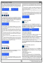
Страница 29: ...an be used to check the voltage set value that is given from remote The button may be locked by the condition LOCK See below About the device Figure 3 Control panel In memory selection mode the button is also used to switch to the voltage set value of the selected memory set but in this mode the set value is not transferred to the output The left display area will then show like this Pushbutton Pr...

Страница 30: ...gue or digital interface the preset mode can be used to check the current set value that is given from remote The button may be locked by the condition LOCK See below In memory selection mode the button is also used to switch to the current set value of the selected memory set but in this mode the set value is not transferred to the output The right display area will then show like this Pushbutton...

Страница 31: ...e 6 3 Further control elements Pushbuttons Rotary encoder Both of the rotary encoders have a push button function Pushing any or both of these will effect following a Fine adjustment mode Fine A short push of any of both buttons activates or deactivates the fine adjustment mode If Fine is active all set values thresholds and limits can be adjusted in smallest possible steps no matter what mode is ...

Страница 32: ...cturer s name address and logo device type and firmware version In the device setup see section Device setup there is an option Outp Rstr output restore that determines the output condition after the device is switched on Default is on It means that the set values of U I P the values of OVP and UVL and the output condition are restored to what was present when the device was switched off the last ...

Страница 33: ... constant current regulation the output voltage is defined by the resistance of the load Then the power is limited down Output voltage and current are decreasing to values according to the formula P U I If the current set value is then decreased the output current would also decrease and thus the output voltage The product of both values the actual power would sink below the previously set power l...

Страница 34: ...terface card This is required if the device is at the end of the bus Following settings only with RS232 interface IF R1 Name Baud Default 57600 Settings 9600 19200 38400 57600 Meaning Selects the serial transmission baudrate in baud Further parameters for the RS232 are not configurable but defined as follows Parity odd Stop bits 1 Data bits 8 and have to be set to the same configuration at the PC ...

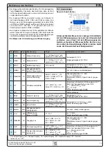
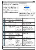
Страница 35: ...age 10V or 5V Accuracy 0 2 at IMax 5mA Short circuit proof against AGND 4 DGND POT Reference potential for digital control signals For Vcc control and status signals 5 REMOTE DI Toggle between internal or external control External LOW ULow 1V Internal HIGH UHigh 4V Internal open U range 0 30V IMax 1mA at 5V Sender Open collector against DGND 6 OT DO Overtemperature error OT HIGH UHigh 4V no OT LOW...

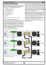
Страница 36: ...s master and any other as slave The slave s are controlled by the master via the slave input pins 3 and 4 of the terminal System Bus Voltage and current can be controlled simultaneously but also seperately For an example wiring see figure 5 Voltage and current are here given by the master In case only one of both voltage or current is going to be controlled the other set value should be set to 100...

Страница 37: ...all have the same nominal output current or all units will have to be read seperately For an example wiring see figure 6 Figure 5 Series connection in Master Slave 11 3 Networking Figure 7 and 8 depict networking examples for the digital control of multiple devices in star shaped USB RS232 or bus like CAN GPIB configuration Limitations and technical specifications of the bus systems and the interf...

Страница 38: ...H Co KG Irrtümer und Änderungen vorbehalten EN 2009 Elektro Automatik GmbH Co KG Operating the device Figure 6 Parallel connection with Share Bus Figure 8 CAN networking example also applies to GPIB Figure 7 USB or RS232 networking ...

Страница 39: ......

Страница 40: ...EA Elektro Automatik GmbH Co KG Entwicklung Produktion Vertrieb Helmholtzstraße 31 33 41747 Viersen Telefon 02162 37 85 0 Telefax 02162 16 230 ea1974 elektroautomatik de www elektroautomatik de ...

Отзывы: