background image

 
Smart-Keyboard eSK-R30B-X


16 

••••


Solution Specification (V1.3) 01.25.2013 

(This specification is subject to change without further notice)


6.2


Pin Assignment 

Pin # 

10 

Signal 

VCC 

GND 

BTN1 

BTN2 

BTN3 

/INT 

SDI 

(MOSI) 

SDO 

(MISO) 

SCK 

/SS 

Connector type: P-TWO 196087-10021-1 10 pins connector or equivalent, pitch is 1.0 

±

 0.10 mm. 

Pin Assignment Description 

Pin 

Signal 

I/O 

Description 

VCC 

Power 

VCC 

GND 

Ground 

Ground 

BTN1 

Physical Button Input # 1, active low. 

The BTN1 is connected to Vcc through a 66 K

 resistor 

inside the TouchPad controller. 

BTN2 

Physical Button Input # 2, active low. 

The BTN2 is connected to Vcc through a 66 K

 resistor 

inside the TouchPad controller. 

BTN3 

Physical Button Input #3, active low. 

The BTN3 is connected to Vcc through a 66 K

 resistor 

inside the 

/INT 

I Interrupt, active low, indicates that the Smart-Pad

TM

 is 

ready to send data


SDI 

(MOSI) 

Master out, Slave in. 

Data from host to Smart-Pad

TM

SDO 

(MISO) 

Master in, Slave out 

Data from Smart-Pad

TM

 to host. 

SCK 

SPI clock in 

10 

/SS 

Slave select in 


Содержание eSK-R30B-X

Страница 1: ...ndows 8 8 8 8 TouchPad TouchPad TouchPad TouchPad Support Support Support Supports s s s for for for for Multi Multi Multi Multi Touch Touch Touch Touch Gesture Gesture Gesture Gesture Solution Specif...

Страница 2: ...tion is furnished under a license or nondisclosure agreement and may be used or copied only in accordance with the terms of such agreement ELAN Microelectronics products are not intended for use in li...

Страница 3: ...____________15 6 1 Touchpad Orientation ______________________________________________15 6 2 Pin Assignment ___________________________________________________16 6 3 Mechanical Drawing _______________...

Страница 4: ...cification Revision History Doc Version Revision Description Date 1 0 Preliminary Specification 2012 07 19 1 1 Updata dongle circuit 2012 08 20 1 2 Additional the LED indicator and Manual syncing step...

Страница 5: ...res the first is that the touchpad is behaved as a multi touch input device which performs Windows 8 multi touch as well the second feature is that the touchpad can sends graphical keypad characters o...

Страница 6: ...Smart Keyboard eSK R30B X 2 Solution Specification V1 3 01 25 2013 This specification is subject to change without further notice 3 System Block Diagram Figure 3 1 Smart Keyboard System Block Diagram...

Страница 7: ...C TP1 VPP R1 C12 0402 SPI_MOSI S8 L2 12nH 0402 DR C18 0402 R1 22K 0402 U3 CAT24C02TD TSOT23 5 1 2 4 3 5 SCL GND VCC SDA WP R8 0R L1 4 7nH 0402 SPI_SDO GND S5 RF_CE SPI_SCK U2 EM78P451SAQ 44pin QFP 2 3...

Страница 8: ...ISO C7 0 1uF 0402 R6 330R TP7 P55 R2 1M 0402 U2 EM78P611G 1 2 3 4 5 6 7 8 9 10 11 12 13 14 15 16 17 18 19 20 21 22 23 24 P77 VUSB OSCI OSCO VSS V3 3 D D P92 P93 P94 VPP P53 P54 OE P55 PGM P56 DATAIN P...

Страница 9: ...fication is subject to change without further notice 5 Main Components List Component Part No Note Keyboard Control MCU EM78P451SAQ Touchpad 83A871 XX11 RF Transceiver EM198860AW Dongle USB MCU EM78P6...

Страница 10: ...CO R OSC I VDD NC NC NC P70 RESET 44 43 42 41 40 39 38 37 36 35 34 P90 1 33 P71 P91 2 32 P72 P92 SDI 3 31 P67 P93 SDO 4 30 P66 P94 SCK 5 29 P65 P95 SS 6 EM78P451SAQ 28 P64 P50 7 27 P63 P51 8 26 P62 P5...

Страница 11: ...Smart Keyboard eSK R30B X Solution Specification V1 3 01 25 2013 7 This specification is subject to change without further notice Figure 5 1c EM78P451SAQ 44 pin QFP Bonding Pad Diagram...

Страница 12: ...40 5 6 P95 SS 715 0 330 5 28 P64 715 0 435 5 7 P50 715 0 435 5 29 P65 715 0 330 5 8 P51 715 0 540 5 30 P66 715 0 225 5 9 P52 715 0 645 5 31 P67 715 0 120 5 10 P53 715 0 750 5 32 P72 715 0 15 5 11 P54...

Страница 13: ...o change without further notice 24 pin QFN EM78P611G P65 P64 P63 P62 P61 P60 24 23 22 21 20 19 P77 1 18 P82 VDD 2 17 P81 OSCI 3 EM78P611G 16 P57 OSCO 4 15 P56 VSS 5 14 P55 V3 3 6 13 P54 7 8 9 10 11 12...

Страница 14: ...Smart Keyboard eSK R30B X 10 Solution Specification V1 3 01 25 2013 This specification is subject to change without further notice Figure 5 1f EM78P611G 24 pin QFN Bonding Pad Diagram...

Страница 15: ...Smart Keyboard eSK R30B X Solution Specification V1 3 01 25 2013 11 This specification is subject to change without further notice...

Страница 16: ...thout further notice EM198860 uses the QFN20 4x4 package EM198860 1 2 3 4 5 6 7 8 9 10 20 18 19 17 16 15 14 13 12 11 CE CSN MISO IRQ VDD3RX VSSPA RFN REP VDDPA VDD3B VSS3A XTALP XTALN DVSS CDVDD VDD3I...

Страница 17: ...Smart Keyboard eSK R30B X Solution Specification V1 3 01 25 2013 13 This specification is subject to change without further notice Figure 5 1i EM198860 20 pin QFN Bonding Pad Diagram...

Страница 18: ...P 13 6 1156 425 12 CE 1447 975 127 925 3 RFN 13 6 1054 425 13 CSN 1447 975 229 925 4 VSSPA 13 6 886 125 14 SCK 1447 975 1319 625 5 VSSPA 13 6 792 625 15 MOSI 1447 975 1421 625 6 VDD3RX 121 975 13 6 16...

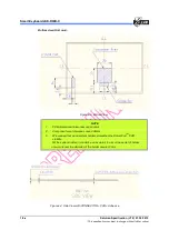
Страница 19: ...ut further notice 6 Touchpad Specifications 6 1 Touchpad Orientation The orientation of the TouchPad is shown as follows The connector part number is P TWO 196087 10021 1 or equivalent device 10PIN 1...

Страница 20: ...N1 I Physical Button Input 1 active low The BTN1 is connected to Vcc through a 66 K resistor inside the TouchPad controller 4 BTN2 I Physical Button Input 2 active low The BTN2 is connected to Vcc thr...

Страница 21: ...to change without further notice 6 3 Mechanical Drawing Physical Specification Overall PCB Dimension Width 107 70 mm Height 71 05 mm Active Area Width 104 1 mm Height 67 50 mm Thickness Please refer...

Страница 22: ...3 Bottom View NOTE 1 PCB dimensional tolerances are 0 3mm 2 Component area tolerances are 0 05mm 3 We suggest that using system holders strengthen the Smart Pad TM PCB stability Put the system holder...

Страница 23: ...gure 6 5 Side View with CONNECTOR PCB Mylar NOTE 1 PCB dimensional tolerances are 0 15mm 2 Component height tolerances are 0 05mm 3 Adhesive thickness tolerance is 0 02mm 4 Mylar thickness tolerance i...

Страница 24: ...alled between the Smart Pad TM and the bezel The insulator might be carved to contain the conductive materials for providing the chassis grounding to enhance the ESD performance b Keep Out Area The co...

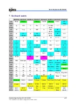
Страница 25: ...S6 I K F6 K56 8 P53 10 5 K 2 K PreTrack 8 K S7 O F7 L APP F8 9 P54 11 6 K NextTrack 3 K K Volume 9 K S8 P K42 _ 0 P83 19 K K K K S9 Scroll FN Alt L Mode Alt R Print P84 20 S10 K14 Backspace F11 Enter...

Страница 26: ...3 This specification is subject to change without further notice 8 Support Gestures Behavior The Smart TouchTM supports various multi finger taps and gestures to perform various functions The related...

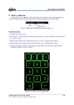
Страница 27: ...witch table 9 1 The mode condition of the ten key function Function descript 1 Support the one key used 2 Invalid action to the finger slide When the finger slide ten key function will keep the first...

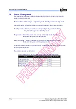
Страница 28: ...de After 1 second of no activity in Operating mode the Smart Keyboard then goes into Standby mode Sleep mode After 10 seconds of no activity in Standby mode the Smart Keyboard then goes into Sleep mod...

Страница 29: ...The Dongle will get into binding mode immediately and the LED indicator on the Dongle will flash per 1 seconds If you have completed the keyboard linkage successfully the LED indicator of the Dongle w...

Отзывы: