background image

24

Chapter 2  Setup

2-4.  Adjustments

Connecting the power cord starts supplying power, and the test pattern appears. Then, the image 
captured by the camera is displayed on the monitor.

Before using this product, it is recommended to con gure some of the settings tailored to your operating

environment.

The settings can be con gured on the menu screen displayed on the monitor. Display the menu in the

procedure described below.

1. 

If the power is turned off, turn on the power switch located on the CCU front 

panel.

2. 

Press the “MENU” button.

The MENU screen appears on the monitor.

Note

 • After a certain period of idle time, the menu screen will exit.
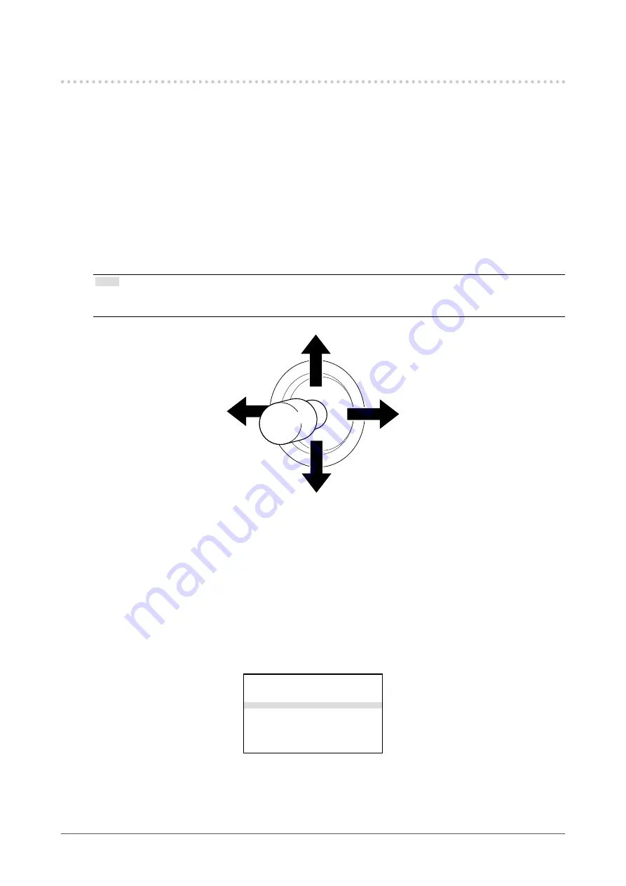
 • Use the joystick to select a menu item.


Setting the Installation Direction

When the camera is installed by hanging from the ceiling, the installation direction must be 

con gured.
By con guring the installation direction, the image will be inverted, allowing the users to perform

intuitive operation.

1. 

Press the “MENU” button.

2. 

Select “Camera & Lens” and press the ”ENTER” button or push the joystick 

toward right.

ALC

=>

Picture

=>

Color

=>

Camera & Lens

=>

Video Output

=>

Audio

=>

Device Setting

=>

Save/Load

=>

Information

=>

Language

English

Содержание CuratOR SC430-PTR

Страница 1: ...iliarize yourself with safe and effective usage Please retain this manual for future reference For the latest product information including the Instructions for Use refer to our web site www eizo or c...

Страница 2: ...unit This product has been adjusted speci cally for use in the region to which it was originally shipped If operated outside this region the product may not perform as stated in the speci cations No...

Страница 3: ...enance please read carefully this section and the caution statements on the product Location of the Caution Statements Bottom of the CCU Symbols on the unit Symbol This symbol indicates Power switch T...

Страница 4: ...a damaged unit may result in re or electric shock Use the unit in an appropriate location Otherwise re electric shock or equipment damage may result Do not place outdoors Do not place in any form of t...

Страница 5: ...damaged cord or AC adapter may result in re or electric shock The operator should not touch the patient while touching the product This product has not been designed to be touched by patients Never to...

Страница 6: ...ter becomes hot during use Do not cover or place anything on top of the AC adapter Do not place the AC adapter on top of things that trap heat such as carpets blankets etc Keep the AC adapter away fro...

Страница 7: ...que to the CMOS imaging elements White spots CMOS imaging elements are known to generate small white spots on the screen in rare instances due to cosmic rays etc This occurs due to the characteristics...

Страница 8: ...ride Welpas Alkyldiaminoethylglycine Tego 51 Glutaral Sterihyde Glutaral Cidex Plus28 Ammonia Ammonia water Hydrogen peroxide Hydrogen peroxide solution Alkyldiaminoethylglycine hydrochloride Satenidi...

Страница 9: ...d Encoders 21 Connecting a Computer Optional 21 Connecting the Power Cord 22 2 4 Adjustments 24 Setting the Installation Direction 24 Adjusting the Brightness 25 Chapter 3 Operation 27 3 1 Camera Cont...

Страница 10: ...to connect the Camera Control Unit CCU with the camera Easy to install and transport Operation Operation on the CCU Control Panel IR remote controller included Communication Control RS 232C LAN Output...

Страница 11: ...Power cord Thread locking uid Camera cable Attention Remove the batteries from the remote controller if it will not be used for a long time 1 A protection cover is attached to the lens at the shipmen...

Страница 12: ...f the remote controller It is the light receiving section of the remote controller Do not block the light receiving section 4 LED Each LED indicator lights up according to the status of this product C...

Страница 13: ...itching the settings are located No ON OFF Description 1 ON Set the switch to OFF OFF 2 ON Set the switch to OFF OFF 3 ON Set the switch to OFF OFF 4 ON PAL 50 Hz mode OFF NTSC 60 Hz mode If the setti...

Страница 14: ...of the remote controller Do not block the light receiving section 3 LED The LED indicator lights up according to the camera status Flashing in green Initializing Lit in green The camera is running Lit...

Страница 15: ...terminal Connects the camera to the CCU with the provided cable 2 MODE switch DIP switches used for switching the settings are located The power is turned off for all the components in the factory de...

Страница 16: ...aves such as transformers and motors Near the equipment emitting radio waves such as walkie talkies and mobile phones Near a radio or TV station emitting strong radio waves Areas affected by the light...

Страница 17: ...the focal length is shorter than 1 5 m attaching the close up lens is recommended Attention With the close up lens attached it is not possible to set the focal point farther than 2m Attention When usi...

Страница 18: ...three locations on the lter attaching area Attention Use the provided thread locking uid The thread locking uid is not an adhesive agent Forcibly rotating the ND lter to left may cause the lter to be...

Страница 19: ...he tightening is not performed correctly the attached part may be damaged which may result in injury or equipment damage Screw tightening torque 1 0 N m to 1 4 N m Required tools Phillips screwdriver...

Страница 20: ...t the camera and CCU using a provided camera cable Attention Use the provided camera cable In case of any damage is found with the cable do not use it Disconnect the power cord During the work be sure...

Страница 21: ...monitor CCU Devices including monitors and encoders Connecting a Computer Optional To control a camera using the application connect CCU to a computer 1 Using a LAN cable or an RS 232C cable connect t...

Страница 22: ...Connect the power cord to the AC IN terminal on the AC adapter Insert the power cord all the way to the back 2 Connect the DC OUT terminal of the AC adapter to the DC IN terminal on the CCU Align the...

Страница 23: ...ertical position Do not use any object covering the AC adapter Secure the adapter using a banding band such as a cable tie as necessary to prevent it from dropping Connecting the power cord starts sup...

Страница 24: ...itch located on the CCU front panel 2 Press the MENU button The MENU screen appears on the monitor Note After a certain period of idle time the menu screen will exit Use the joystick to select a menu...

Страница 25: ...following settings tailored to your operating environment Changing the ALC Level If it is too bright or too dark change the ALC level 1 Press the MENU button The MENU screen appears on the monitor 2 S...

Страница 26: ...and press the ENTER button or push the joystick toward right ALC Picture Color Camera Lens Video Output Audio Device Setting Save Load Information Language English 3 Select White Balance WB push the...

Страница 27: ...ressing the FAR button to focus farther Keep pressing the NEAR button to focus closer Press the AF button to execute the OnePush AF Hold down the AF button approx 2 sec to switch to the real time AF P...

Страница 28: ...28 Chapter 3 Operation 3 2 Menu Operation ENTER Display Menu Exit Right Up Down Left Go back Up Right Down ENTER Left Go back Display Menu Press Hold Exit...

Страница 29: ...ed manually and the shutter speed and gain setting are adjusted automatically Manual The shutter iris and gain settings are adjusted manually Level 4 0dB 4 0dB The ALC brightness level is speci ed Th...

Страница 30: ...ntended increase of the gain and noise generation This setting can be con gured when ALC Mode is set to Full Auto Shutter Priority or Iris Priority Center Weighted Metering Off On If the center part o...

Страница 31: ...environment OnePush The white balance is adjusted when the Execute button is pressed Once the adjustment is complete the color tone is retained The conditions for the object s surroundings are not af...

Страница 32: ...LT Speed 1 7 1 The TILT speed is adjusted ROLL Speed 1 7 1 The ROLL speed is adjusted Installation Direction Normal CeilingSuspended The installation direction is adjusted Selecting CeilingSuspended c...

Страница 33: ...tput SDI Output Mode 1080p 1080i Select a resolution for the output from 2K SDI HDMI Output Mode 1080p 1080i Select a resolution for the output from 2K HDMI HDMI Color Space RGB Limited RGB Full YUV42...

Страница 34: ...vely Gateway Specify the gateway Fill in Addr0 Addr1 Addr2 and Addr3 respectively Apply The network settings are applied It is enabled only when the network settings are modi ed Option Button Off PTR...

Страница 35: ...ings including the network settings and saved settings will be reset USB Memory Save settings to USB memory Load settings from USB memory The settings are saved into and loaded from a USB memory The f...

Страница 36: ...Information The equipment information for this product is displayed The information is displayed for viewing only It cannot be modi ed Information 1 3 Maintenance Model Name SC430 PTR Ethernet Connect...

Страница 37: ...R xx xx xxxx R xx xx xxxx Information on the CCU is displayed Information 3 3 Version Model Name SC430 PTR PTR Serial No xxxxxxxx Version R xx xx xxxx Camera Serial No xxxx xxxx xx Version Vxxx Featu...

Страница 38: ...uired for using this function Please prepare it separately Make sure that the USB memory is writable If it is not writable an error message appears 1 Insert a USB memory into the USB terminal on the C...

Страница 39: ...s to USB memory and press the ENTER button or push the joystick toward right USB Memory Save settings to USB memory Yes Load settings from USB memory No Restart automatically after loading 7 Press the...

Страница 40: ...tton or push the joystick toward right ALC Picture Color Camera Lens Video Output Audio Device Setting Save Load Information Language English 4 Push the joystick toward right and display Device Settin...

Страница 41: ...ation Camera Lens page 32 Zoom Speed Focus Speed PAN Speed TILT Speed ROLL Speed Installation Direction ROLL Angle Sync Zoom Position Sync Video Output page 33 4K Output SDI Mode SDI BT 2020 Emulation...

Страница 42: ...6 Information 1 3 Maintenance Model Name Ethernet MAC Address IP Address Subnet Mask Gateway FPGA Temp C Information 2 3 Version Model Name CCU Serial No Version MCPU BOOT MCPU SCPU FPGA FPGA CPU Info...

Страница 43: ...Video Output Format set to Camera See 4 5 Video Output page 33 7 2 Other Problems Problem Possible cause and remedy 1 The camera does not move Are all the MODE switches of the camera turned off See 2...

Страница 44: ...mera 1 POWER Lit in blue CAMERA Flashing in yellow LOCK MAINTENANCE A camera is connected POWER Lit in blue CAMERA Lit in yellow LOCK MAINTENANCE Key lock is activated 2 POWER Lit in blue CAMERA LOCK...

Страница 45: ...English 45 Chapter 7 Troubleshooting Camera Front LED status Product status Flashing in red The inside of the camera is extremely hot Or the camera was brought to an emergency stop...

Страница 46: ...ft Right Top Bottom and Left Right Invert Video Format 4K HDMI 2160 59 94p 2160 50p SDI 2160 59 94p 2160 50p 2K HDMI 1080 59 94p 1080 59 94i 1080 50p 1080 50i SDI 1080 59 94p 1080 59 94i 1080 50p 1080...

Страница 47: ...mensions CCU Unit mm 212 212 212 270 12 5 300 5 43 18 3xM4 MAX depth 13mm 3xM4 MAX depth 13mm 43 14 40 87 5 24 14 40 24 Camera 153 198 100 25 162 4xM4 MAX depth 30mm 59 65 7 180 150 79 19 5 59 90 208...

Страница 48: ...e via a medium such as CD ROM at a cost to individuals and organizations who make contact via the following contact information for a minimum period of three years after purchase of the product We wil...

Страница 49: ...y the equipment or system should be observed to check for normal operation in the con guration in which it will be used When using portable RF communication equipment keep it 30 cm 12 inches or more a...

Страница 50: ...ironments Compliance level Electromagnetic environment Guidance Electrostatic dis charge ESD IEC EN61000 4 2 8 kV contact discharge 15 kV air discharge 8 kV contact discharge 15 kV air discharge Floor...

Страница 51: ...hould be less than the compliance level in each frequency range b Interference may occur in the vicinity of equipment marked with the following symbol Note 1 UT is the a c mains voltage prior to appli...

Страница 52: ...WLAN 802 11 a n Pulse modulation b 217 Hz 0 2 0 3 9 9 5500 5785 a For some services only the uplink frequencies are included b Carrier waves are modulated using a 50 duty cycle square wave signal The...

Страница 53: ...ith the instruction manual may cause harmful interference to radio communications Operation of this equipment in a residential area is likely to cause harmful interference in which case the user will...

Страница 54: ...possible technical innovations and or regulations c Any deterioration of the sensor including measurement value of the sensor d Any defect of the Product caused by external equipments e Any defect of...

Страница 55: ...af li e de votre pays Les adresses des distributeurs sont r pertori es sur le site Web EIZO ci dessous www eizoglobal com Pour les clients en Suisse veuillez consulter le site Web suivant a n d obten...

Страница 56: ...bortskaffer denne produkt skal du kontakte en distribut r eller et tilknyttet selskab i dit land Adresserne p kontaktpersonerne er angivet p EIZO s websted nedenfor www eizoglobal com Kierr tyst koske...

Страница 57: ...krajiny aby sa zn ilo za a enie ivotn ho prostredia Ke sa chcete zbavi tohto v robku kontaktujte pros m distrib tora alebo pobo ku vo va ej krajine Zoznam kontaktn ch adries je uveden na nasledovnej w...

Страница 58: ...ili inin azalt lmas konusundaki mevzuat na g re toplanmas ve yeniden de erlendirilmesi gerekmektedir r n ataca n z zaman l tfen lkenizdeki bir distrib t r veya ilgili kurulu la temasa ge iniz rtibat a...

Страница 59: ...English 59...

Страница 60: ...s reserved 1st Edition April 2019 Printed in Japan 00N0N126A1 IFU SC430 PTR 3 www eizo or com Helmut Grashoff Strasse 18 41179 M nchengladbach Germany 153 Shimokashiwano Hakusan Ishikawa 924 8566 Japa...

Отзывы: