EEC ESD-140 Скачать руководство пользователя страница 20


16 


Step 

Each of the 10 memory locations in ESD-140 has 3 programmable test steps that may 
be connected together to create a multi-step test sequence

.  Press the “Step” soft key 

to increment the test step number. 
 

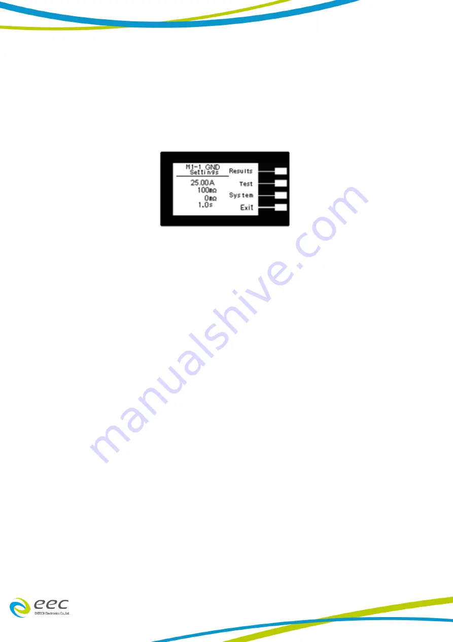
4.1.3 Results, Tests and System Selections 

From the Main Menu

, press the “Menu” soft key.   


From this screen, three software controls may be accessed: Results, Test and System.  
Pressing the “Exit” soft key at any time will return you to the Main Menu screen.   


Results 

Pressing the “Results” soft key from this menu will allow you to review the test results 
of the last test performed.  


Test 

Pressing the “Test” soft key from this menu will allow you to access the Parameter 
Review screen.  For specific instructions for reviewing and editing test parameters, 
refer to section 

4.3. Test Parameters

.   


System 

Pressing the “System” soft key from this menu will allow you to access the Setup 
System screen.  For specific instructions for editing system parameters, refer to 
section 

4.2. System Setup

.  


4.2 System Setup 


1. 

From the Perform Tests screen, press the “Menu” soft key. The Main Menu screen 
will now be displayed. 

2.  From the Main Menu screen,


press the “Menu” soft key.  Results, Test and System 

selections will now be displayed. 

3. 

From this screen, press the “System” soft key.  The Setup System Menu will now 
be displayed. 

 
From the Setup System screen, fourteen different hardware and software controls 
may be accessed: PLC Remote, Single Step, Alarm, Contrast, Results, Lock, Mem 
Lock, Hipot Start, Cal-Alert, Cal Date, Cal Due, Alert, Date, and Time.  Pressing the 
“Exit” soft key at any time will save all parameters and return to the Perform Tests 
screen.   
 

Содержание ESD-140

Страница 1: ...ESD 140 DC Ground Bond Tester Operation Manual E 1 01...

Страница 2: ......

Страница 3: ...ly or the whole unit Any non authorized modifications tampering or physical damage will void your warranty Elimination of any connections in the earth grounding system or bypassing any safety systems...

Страница 4: ...se in non residential non domestic environments Use of the product in residential domestic environments may cause electromagnetic interference 2 Connection of the instrument to a test object may produ...

Страница 5: ...ment Controls 13 4 Programming Instructions 15 4 1 Power Up 15 4 2 System Setup 16 4 3 Test Setup 21 5 Operating 24 5 1 Instrument Connections 24 5 2 Performing a Test 25 5 3 Test Metering 25 5 4 Resu...

Страница 6: ...ommonly in the U S A 60 per second in other countries 50 times per second Breakdown The failure of insulation to effectively prevent the flow of current sometimes evidenced by arcing If voltage is gra...

Страница 7: ...flow is directly proportional to voltage The insulation and or capacitance are thought of as a constant impedance unless breakdown occurs Resistance That property of a substance that impedes current...

Страница 8: ...ream of activity which employees do not walk through in performing their normal duties If this is not practical because of production line flow then the area should be roped off and marked for HIGH VO...

Страница 9: ...c shock and must only be operated by a skilled worker trained in its use The operator should understand the electrical fundamentals of voltage current and resistance They should recognize that the tes...

Страница 10: ...1 3 5 Key Safety Points to Remember Keep unqualified and unauthorized personnel away from the test area Arrange the test station in a safe and orderly manner Never touch the product or connections du...

Страница 11: ...s and outputs for simple PLC relay control Outputs include PASS FAIL RESET and TEST IN PROCESS signals Inputs include TEST INTERLOCK RESET and remote recall of MEMORY 1 2 and 3 WITHSTAND PROCESSING IN...

Страница 12: ...t 1137 Current with Kelvin Cable ASSY High Current Return 1138 Return with Kelvin Fuse 10 Amp Slow Blow 250VAC Power Cord Standard Interlock Connector 1505 Only accessories that meet the manufacturer...

Страница 13: ...ed in a socket outlet with a protective ground earth contact This protective ground must not be defeated by the use of an extension cord without a protective conductor Do not replace the included line...

Страница 14: ...e 40 75 C Altitude 25000 feet 7 620 meters The instrument should also be protected against temperature extremes that may cause condensation within the instrument Ventilation Do not block any ventilati...

Страница 15: ...00A 30 01 40 00 Resolution 1 m Accuracy 3 of reading 3 counts 2 of reading 2 counts GENERAL Input Voltage AC 100 120V 10 200 240V 10 auto detection 50 60 Hz 10 Amp slow blow 250 VAC PLC Remote Control...

Страница 16: ...lder Interlock Disable Key 1505 1 Ground Bond Test Lead 40A 1 6m 1137 1 Ground Bond Return Lead 40A 1 6m 1138 1 product specifications are subject to change without notice Ordering Information ESD 140...

Страница 17: ...the display 3 GRAPHIC LCD 128 X 64 Monographic LCD 4 SOFT KEYS Multifunction parameter selection keys Keys used to select screens and change parameters 5 SENSE JACK Connector used to attach the Curre...

Страница 18: ...MA style line power mains cord 4 CHASSIS GROUND EARTH TERMINAL This terminal should be connected to a good earth ground before operation 5 THERMAL COOLING FAN Full time cooling fan 6 CALIBRATION BUTTO...

Страница 19: ...played when the Connect function has been turned ON NOTE There are only 3 programmable test steps per memory location Step 3 of any memory location cannot be connected to another step 4 1 2 Main Menu...

Страница 20: ...for reviewing and editing test parameters refer to section 4 3 Test Parameters System Pressing the System soft key from this menu will allow you to access the Setup System screen For specific instruct...

Страница 21: ...PLC Remote function is turned ON a pop up message will be displayed Refer to the section 6 Connection of Remote I O for more details Single Step This function is used to temporarily override the auto...

Страница 22: ...ll be displayed at the end of the test The Pass and Fail screens will appear as follows When P F is selected it is not possible to see the test results directly at the end of the test In order to revi...

Страница 23: ...instrument will display the Cal Alert warning screen upon power up If the Show this screen again function has been turned OFF at the Cal Alert Warning screen this parameter will automatically be set...

Страница 24: ...ords Yes and No using the corresponding soft key and then pressing the OK soft key Selecting No will disable the Cal Alert function Selecting Yes will exit the Cal Alert Warning screen and go to the s...

Страница 25: ...displayed 2 From the Main Menu screen press the Menu soft key Results Test and System selections will now be displayed 3 From this screen press the Test soft key The Test Parameter Review screen will...

Страница 26: ...test fixture resistance during the test Using the up and down arrow keys scroll the cursor to the Offset parameter and press the Edit soft key You may now manually or automatically set an Offset value...

Страница 27: ...the and soft keys to the Current parameter Press the Edit soft key Increase or decrease the Current parameter using the up and down arrow keys Press the Enter soft key to accept the parameters or pres...

Страница 28: ...ect the High Current lead to the Current receptacle on the ESD 140 then connect the Kelvin lead smaller gauge wire captured in the same sleeve to the SENSE receptacle Next connect the other end of the...

Страница 29: ...see section 4 2 Setup System for more information To access the results screen use one of the following methods Method 1 Hot key Pressing the bottom soft key at the Perform Tests screen will display t...

Страница 30: ...well beyond the metering range of the test Interlock Open This message appears on the display if the Remote Interlock feature is activated before or during a test See section 6 2 Remote Signal Inputs...

Страница 31: ...cate the condition of the tester The RESET OUT pulse signal and the START OUT pulse signal are also provided by a normally open internal relay The RESET OUT gives a signal whenever the RESET function...

Страница 32: ...und Bond Tester and a connected eec Hipot The parameter controls if the Hipot will run after the Ground Bond Tester has completed its test G W or if the Hipot will run at the same time as the Ground B...

Страница 33: ...quipped with a Remote Interlock feature Remote Interlock utilizes a set of closed contacts to enable the instrument s output If the Remote Interlock contacts are open the output of the instrument will...

Страница 34: ...dicator will appear in the upper right of the display PLC Remote Pop up message If you attempt to start a test from the front panel TEST button and the PLC remote function is turned ON a pop up messag...

Страница 35: ...ecting the Ground Bond Tester with an eec HIPOT Tester The parameter determines if the Hipot will run after the Ground Bond Tester has completed its test G W or if the Hipot will run at the same time...

Страница 36: ...ill return with 06 hex or 6 decimal the Acknowledge ACK ASCII control code If there is an error with the command string that is sent the instrument will respond with 15 hex or 21 decimal the Not Ackno...

Страница 37: ...fset for the ground bond test The cables and any test fixture should be connected before executing the command This command will perform an actual test and all safety precautions should be observed wh...

Страница 38: ...modify the test parameter within each step These commands require a parameter value to be included with the command The writing of the parameter requires that the unit not be included with the value...

Страница 39: ...t the order of which the steps were executed For example if the test was executed starting from step 2 and ending with step 3 then the first step test results will be found in location 2 not in locati...

Страница 40: ...he option to press the TEST button and activate the Verification Menu The option to activate verification expires approximately 3 seconds after power up 8 2 Verification Menu From the Initialization s...

Страница 41: ...37 If the instrument fails the Verification test pass indicating the fail detectors are not working properly the following message will appear...

Страница 42: ...calibration mode Required Calibration Equipment 40 Amp DC Ammeter 10 VDC Voltmeter 9 1 Calibration Initialization Press and hold the Calibration key on the rear panel with a pen pencil or small screw...

Страница 43: ...39 9 1 2 Calibration of Ground Bond DC Current...

Отзывы: