Configuration
RCX C-Link User’s Guide
9
EDT, Inc. November 2006
If you’re using the RCX C-Link with a PCI DV FOX fiber optic frame-grabber, you need to set a blink
code at the camera end only.
Blink Codes for Base-mode Systems
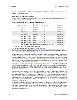
An RCX C-Link module running firmware revision 11 or higher with base-mode cameras offers the
operating modes shown in
Table 1
.
Most base-mode Camera Link cameras operate between 20 and 40 MHz, so use blink codes of 1-1
at the camera end and 2-1 at the frame-grabber end.
Blink code 2-1 at the frame-grabber end of an extension cord regenerates a constant 40 MHz pixel
clock to the frame-grabber asynchronous to the camera’s actual clock; this is also suitable for cameras
operating between 20 and 40 MHz. Data for an entire raster is accumulated, then sent to the frame-
grabber in one burst. The regenerated clock at the frame-grabber end must be at least as fast as the
camera clock at the camera link interface; for each frame-grabber blink code, this regenerated clock
rate is given in the Camera Clock Rate column.
If the raster is very long and if the regenerated frame-grabber end clock is much faster than that of the
camera, the frame-grabber end RCX C-Link may have to drop Data-Valid mid-raster and wait for
additional data from the camera. This seldom occurs, and most frame-grabbers can handle it and
continue normal operation.
Cameras operating between 40 and 60 MHz are usually best served by blink codes 1-3 and 2-3. If the
camera needs only 16 data bits or fewer transferred per clock cycle (instead of all 24), it is possible to
use blink codes 1-2 and 2-2 instead, and thus operate the link at 1.25 GBaud for longer range and
lower power dissipation. The selection of 16-bit mode is made only at the frame-grabber end through
blink code 2-2, or through the
mode16:
1
directive in a PCI DV FOX configuration file; this information
is communicated over the fiber to the RCX C-Link at the camera end. (At the camera end, blink codes
1-1 and 1-2 are identical.)
At reset (and whenever the RCX C-Link cannot lock to the camera clock), the RCX C-Link initializes
to assume that the Camera Link Data-Valid signal is never asserted, and ignores it. Many Pulnix
cameras do not assert Data-Valid, so this behavior is useful for those using such cameras. The first
occurrence of Data-Valid true from the camera causes the RCX C-Link to use Data-Valid to qualify
video data from that point on.
Table 1. Base-mode Blink Codes and Operating Modes
Blink Code End
Camera
Clock Rate
Constraints
Link Rate
1-1 camera
20–40 MHz
24 bits
1.25 GBaud
1-2 camera
20–60 MHz
16 bits
1.25 GBaud
1-3 camera
20–60 MHz
24 bits
2.5 GBaud
1-4 camera
60–80 MHz
24 bits
2.5 GBaud
2-1 frame-grabber
40 MHz
24 bits
1.25 GBaud
2-2 frame-grabber
60 MHz
16 bits
1.25 GBaud
2-3 frame-grabber
60 MHz
24 bits
2.5 GBaud
2-4 frame-grabber
80 MHz
24 bits
2.5 GBaud
3-3 firmware update ( See
Updating the Firmware on page 12
.)
1.25 GBaud
2 fast, 2 slow, 2 fast Error: unsupported code entered
For additional LED blinking behavior, see
LED Status on page 8
.


