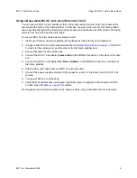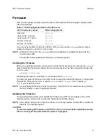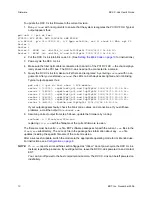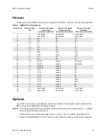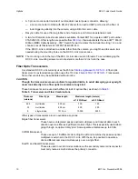
Using the RCX C-Link in Base Mode
RCX C-Link User’s Guide
3
EDT, Inc. November 2006
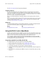
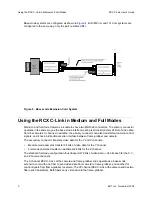
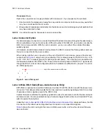
Figure 3. Connecting the RCX C-Link to a Camera
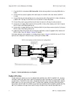
6. Attach a fiber optic cable from the RCX C-Link to channel 0 of the PCI DV FOX — channel 0 is
the connector physically closest to the PCI bus.
7. Connect the power supply provided to the power connector on the back of the RCX C-Link.
8. Turn power back on to all devices.
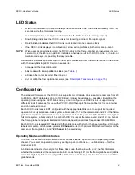
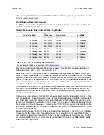
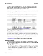
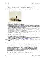
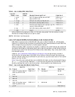
9. Verify that the LED on the RCX C-Link and the Channel 0 LED on the PCI DV FOX show a solid
green light when power is applied to the camera and RCX C-Link. See
LED Status on page 8
for
details.
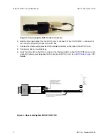
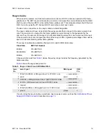
Figure 4. Base-mode System With PCI DV FOX


