RCX C-Link User’s Guide
Using the RCX C-Link in Medium and Full Modes
EDT, Inc. November 2006
6
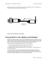
Many frame-grabbers require that video data presented at the primary and secondary connectors be
synchronized to within a fraction of a pixel clock. The
Resync Cable
described on
page 18
provides a
common pixel clock to both RCX C-Links at the frame-grabber, and other synchronizing signals to
ensure that the starting pixel of each raster lines up across the X, Y and Z channels. The resync cable
also supplies power to the RCX C-Links.
NOTE
To avoid damaging a component, ensure that the entire system is properly connected before
applying power to any of the components. In particular, do not apply power to the resync cable
while connecting or disconnecting it from the RCX C-Links.
Using a Medium-mode RCX C-Link With a PCI DV FOX
Full mode with the PCI DV FOX frame-grabber is of limited use due to the PCI DV FOX’s bandwidth
limit of 200 MB per second.
To connect your medium-mode system:
1. Install the software driver as instructed in the
PCI Digital Video User’s Guide
.
2. Configure the RCX C-Links as described in the
Setting the Blink Code on page 10
.
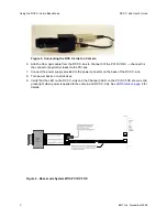
3. Turn off power to the RCX C-Links, the camera, and the host computer.
4. Plug the RCX C-Link labeled
X Channel Camera
into the camera’s primary MDR-26 connector.
5. Plug the RCX C-Link labeled
Y Channel Camera
into the camera’s secondary MDR-26 connec-
tor.
6. Connect the two power supplies with coaxial power connectors to the two camera-end RCX
C-Links.
7. Connect an LC duplex fiber from the X channel RCX C-Link at the camera end to channel 0 of the
PCI DV FOX — the connector physically closest to the PCI Bus.
8. Connect an LC duplex fiber from the YZ channel RCX C-Link at the camera end to channel 1 of
the PCI DV FOX — the connector physically farthest to the PCI Busd.
9. Verify that the LEDs on the RCX C-Links and the Channel 0 LED on the PCI DV FOX show a solid
green light when power is applied to the camera and RCX C-Links. See
LED Status on page 8
for
details.
Using a Medium- or Full-mode RCX C-Link As an Extension Cord
Cameras operating in Camera Link medium or full modes require two RCX C-Link modules at each
end for data transfer. Each of the four RCX C-Link modules in a full-mode system is physically different
from the others. They are not interchangeable simply by changing blink codes.
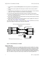
To connect your system:
1. Install your Camera Link frame grabber and software as instructed by its manufacturer.
2. Configure the RCX C-Links as described in the
Setting the Blink Code on page 10
.
3. Turn off power to the RCX C-Links, the camera, and the host computer.
4. Plug the RCX C-Link labeled
X Channel Camera
into the camera's primary MDR-26 connector.
5. Plug the RCX C-Link labeled
YZ Channel Camera
into the camera's secondary MDR-26 connec-
tor.
6. Plug the RCX C-Link labeled
X Channel FG
into the frame-grabber's primary MDR-26 connector.


