EDI SmartMonitor MMU-16LE Series Скачать руководство пользователя страница 21

MMU-16LE 

SmartMonitor


Operations Manual 

Eberle Design Inc. 

Page 15 

3.7 RECURRENT PULSE DETECTION  

This error detection function supplements the normal Conflict, Dual Indication, and Red Fail 
monitoring algorithms for sensing faults which are intermittent or pulsing in nature.  The 
RMS-Engine

®

  is designed to filter out short term transients commonly found on the 

electrical service and provide noise immunity against false signal detections. The Recurrent 
Pulse detection function is designed to respond to fault conditions which are intermittent in 
nature and do not meet the continuous timing requirements of the normal detection 
algorithms, yet may still produce improper signal displays.  These input conditions are 
differentiated by their longer time constant and fault response times. 

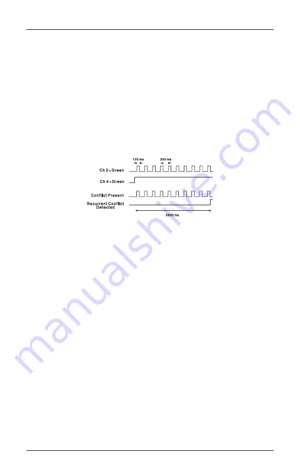
The figure below shows a simple example of a Recurrent Conflict fault. Channel 2 Green is 
detected active due to a malfunction of the load switch which caused the output to “flicker” 
On for 100 ms approximately every 200 ms. Because  normal Conflict detection requires a 
continuous fault of at least 350 ms typical, this event could go undetected. The Recurrent 
Pulse detection algorithm will process  these pulses into one event and trigger a Conflict 
fault once the longer recurrent timing threshold is exceeded. 


When triggered by a recurrent pulse fault condition, the MMU-16LE 

SmartMonitor

®


will 

enter the fault mode, transfer the Output relay contacts to the Fault position, and display 
the appropriate RP  CONFLICT,  RP  DUAL  INDICATION, or RP  RED FAIL status screen. 
The unit will remain in the fault mode until reset by the Reset button or the External Reset 
input. Fault response times will vary depending on the pulse width and frequency of the 
recurrent inputs, but typically range from 1000 ms minimum to 10 seconds maximum.  

This function can be disabled by a UNIT Option called RECURRENT PULSE in the SET / 
VIEW CONFIG menu. See Section 6.3.4.1. 

3.8 TYPE FAULT  

The TYPE SELECT input is used by the MMU-16LE 

SmartMonitor

®


to specify whether the 

monitor is to be configured as a Type 16 unit with 16 channels or a TS1 compatible Type 
12 unit with 12 channels (see Section 1.4.2). This input is read by the MMU-16LE 

SmartMonitor

®


only during power-up initialization or when the unit is reset by the RESET 

button or EXTERNAL RESET input. The Type Select configuration of the MMU-16LE 

SmartMonitor

®


can only be modified when the unit is reset by the RESET button or 

EXTERNAL RESET input. This prevents the possibility of the MMU-16LE 

SmartMonitor

®


changing its configuration mode due to the failure of the cabinet TYPE SELECT jumper or 
the monitor TYPE SELECT input.  

Once the unit is programmed by a reset command, its configuration mode (Type 16 or Type 
12) is stored in non-volatile memory. During power-up initialization, the MMU-16LE 

SmartMonitor

®


compares the programmed configuration mode with the state of the TYPE 

SELECT input. If they are different, the MMU-16LE 

SmartMonitor

®


will enter the fault mode, 

transfer the OUTPUT relay contacts to the Fault position, and display the TYPE 12/16 
FAULT status screen. The MMU-16LE 

SmartMonitor

®


will remain in the fault mode until the 

unit is reinitialized with the TYPE SELECT input in the proper state or the MMU-16LE 

SmartMonitor

®


is reset by the RESET button or the EXTERNAL RESET input. 


Содержание SmartMonitor MMU-16LE Series

Страница 1: ...NICAL INFORMATION FOR THE MMU 16LE and MMU16LEip SmartMonitor SERIES MALFUNCTION MANAGEMENT UNIT REVISION APRIL 2012 pn 888 0116 001 MMU 16LE Series SmartMonitor NEMA TS 2 Enhanced Malfunction Management Unit Operations Manual ...

Страница 2: ...N OR USE IN WHOLE OR PART IS NOT PERMITTED EXCEPT UNDER TERMS AGREED UPON IN WRITING COPYRIGHT 2004 2012 EDI Canadian Patent No 2 574 101 U S Pat No 7 246 037 THIS EBERLE DESIGN INC MALFUNCTION MANAGEMENT UNIT HAS BEEN CAREFULLY INSPECTED AND TESTED TO ENSURE PROPER OPERATION IT IS RECOMMENDED THAT THE MALFUNCTION MANAGEMENT UNIT BE TESTED AT LEAST ANNUALLY TO ENSURE PROPER OPERATION AND COMPLIANC...

Страница 3: ...able Input 7 2 2 2 Walk Disable Option 7 2 3 Voltage Monitoring 8 2 3 1 24Vdc Supply Monitoring 8 2 3 1 1 24Vdc Monitor Inhibit Input 8 2 3 1 2 24Vdc Monitor Latch Input 8 2 3 1 3 24Vdc Monitor II 12Vdc Mode 8 2 3 2 Controller Voltage Fault Monitor Input 8 2 3 2 1 CVM Monitor Latch Input 9 2 3 2 2 CVM Log Disable 9 2 4 Local Flash Status Input 9 2 5 Minimum Yellow Change Red Clearance Monitoring 9...

Страница 4: ...ult PF Event Log 25 4 1 4 AC Line AC Event Log 25 4 1 5 Manual Reset MR Event Log 26 4 1 6 Configuration CF Event Log 26 4 1 7 Signal Sequence Event Log 26 4 2 Configuration Programming 26 4 2 1 ECcom Configuration Set up Wizard 26 4 3 Ethernet LAN Port 26 Section 5 Menu Operation 27 5 1 Main Status Menu 27 5 2 Top Level Menu 27 5 2 1 Status 27 5 2 2 Menu 28 5 2 2 1 View Logs 28 5 2 2 2 View and S...

Страница 5: ...Channel Assignments 37 Section 7 Front Panel Description 38 7 1 Main Status Display 38 7 2 Channel Status Display 38 7 3 Front Panel LED Indicators 38 7 3 1 Power Indicator 38 7 3 2 Fault Indicator 38 7 3 3 Diagnostic Indicator 38 7 3 4 Receive Indicator 38 7 3 5 Transmit Indicator 38 7 3 6 COMM Indicator 38 7 4 Front Panel Buttons 39 7 4 1 Reset Button 39 7 4 2 Menu Control Buttons 39 7 4 2 1 Nex...

Страница 6: ...ck Mount Connector 46 10 5 Programming Card Pin Connections 47 10 5 1 Programming Card P1 Connector 47 10 5 2 Programming Card P2 Connector 48 10 6 Port 1 Connector 49 10 7 EIA 232 Connector 49 10 7 1 EIA 232 Cable to a PC 50 10 8 Ethernet LAN Port J2 50 10 8 1 Ethernet LAN Cable 50 ...

Страница 7: ... display showing full intersection status 1 2 2 MENU DRIVEN OPERATION The Display Program and Help modes of the MMU 16LE SmartMonitor are controlled using a simple menu driven user interface The menu provides an organized scheme for displaying both current status as well as reviewing historical fault status It also provides a mechanism for setting and reviewing the monitor enhanced feature program...

Страница 8: ...hen analyzing fault data to diagnose cabinet equipment malfunctions The Signal Sequence logs provide a graphical display of the signal states of all sixteen channels for up to thirty seconds prior to the fault trigger point at 50 millisecond resolution The MMU 16LE SmartMonitor stores these signal records for the last five fault events The EDI ECcom software Version 3 5 8 or greater is required is...

Страница 9: ...Green or Yellow or Walk field signal inputs between any two or more channels not assigned to be permissive on the Program Card The RED ENABLE input when activated enables the Red Fail Monitoring functions of the unit causing the monitor to trigger when it detects the absence of voltage on all three four of the field signal inputs of a channel It also enables the Minimum Yellow Change Red Clearance...

Страница 10: ...nce characteristics such as caused by dimmers burned out lamps low wattage equipment or no load it may be necessary to place a low impedance device external to the unit between the MMU input and AC NEUTRAL See Sections 5 5 3 9 and 6 2 4 of NEMA Standards Publication TS2 2003 v02 06 Traffic Controller Assemblies With NTCIP Requirements The Eberle Design MMU 16LE SmartMonitor can be configured to us...

Страница 11: ...ovide the Port 1 EIA 485 communications port The Controller Unit must be configured for MMU operation in the following areas terminology and procedure may vary with different brands of CU a Enable the MMU in the CU Port 1 setup b Add the Ped channels to the CU ring structure with the following assignments Ped Phase MMU Channel Phase 2 Ped 13 Phase 4 Ped 14 Phase 6 Ped 15 Phase 8 Ped 16 c The CU Si...

Страница 12: ...red for 16 channel operation but the TYPE SELECT input is not accessible due to cabinet wiring issues the MMU 16LE SmartMonitor can be forced to the Type 16 mode by setting the FORCE TYPE 16 option in Unit Options See Section 6 3 4 8 The FORCE TYPE 16 mode is not compatible with the TYPE 12 WITH SDLC mode section 1 4 2 1 ...

Страница 13: ...lt position Red Fail Monitoring will be disabled when the RED ENABLE input is not active In the Type 16 mode Red Fail Monitoring will also be disabled if the LOAD SWITCH FLASH bit is set to 1 in the Type 0 message from the Controller Unit Programming is provided in the SET VIEW CONFIG menu item to enable Red Fail Monitoring on a per channel basis See Section 6 3 3 for the programming procedure 2 2...

Страница 14: ...BIT INPUT A 24V MONITOR INHIBIT input is provided to inhibit the operation of the 24Vdc Monitor Application of a logic TRUE low state to this input will disable the operation of the 24Vdc Monitor 2 3 1 2 24VDC MONITOR LATCH INPUT A jumper position is supplied on the Programming Card to allow 24Vdc failures to latch in the fault condition until the unit is reset by the activation of the RESET butto...

Страница 15: ...UM YELLOW CHANGE INTERVAL The MMU 16LE SmartMonitor will verify that the Yellow Change interval is at least the Clearance Fail Fault time Section 9 The Yellow Change interval consists of the duration of time in which the Yellow field signal input is active in a sequence from Green to Yellow to Red When this minimum interval is not satisfied the MMU 16LE SmartMonitor will enter the fault mode trans...

Страница 16: ...wer Fail Restore time Section 9 the monitor will resume normal operation and the POWER indicator on the front panel will remain illuminated After a 2 0 _ This expanded operating voltage range for cabinet components allows the MMU 16LE SmartMonitor to place the intersection into flash and return to normal operation in an orderly manner when the AC LINE voltage is sufficient for proper operation The...

Страница 17: ...on and display the PORT 1 FAIL status screen When receipt of a Type 0 message again occurs the MMU 16LE SmartMonitor will exit the fault state and transfer the OUTPUT relay contacts to the normal position except when three Port 1 faults have occurred in a calendar day After the third Port 1 fault in a calendar day the MMU 16LE SmartMonitor will remain in the fault mode until the unit is reset by t...

Страница 18: ...2 6 Due to the nature of these hardware firmware failures other fault indicators that may be concurrently displayed with the DIAGNOSTIC indicator may not be valid 2 10 2 MICROPROCESSOR MONITOR The MMU 16LE SmartMonitor contains circuitry which monitors the operation of the internal microprocessor This monitoring circuit receives a logic transition signal from the microprocessor every 5 msec When t...

Страница 19: ... be displayed upon restoration of AC Line power This EEPROM device requires no battery back up The time of day in the MMU 16LE SmartMonitor is stored in a battery backed real time clock circuit Should this battery fail only current time of day and date information will be lost No monitor configuration programming is stored under battery power 3 2 DUAL INDICATION MONITORING In Type 16 mode this mon...

Страница 20: ... External Watchdog fault has been detected The MMU 16LE SmartMonitor will remain in the fault mode until the unit is reset by the RESET button or the EXTERNAL RESET input An MMU Power Failure will also reset the External Watchdog fault state of the monitor see Section 2 6 This function is enabled by a UNIT Option called EXTERN WATCHDOG in the SET VIEW CONFIG menu see Section 6 3 4 4 The EXTERNAL W...

Страница 21: ...unit will remain in the fault mode until reset by the Reset button or the External Reset input Fault response times will vary depending on the pulse width and frequency of the recurrent inputs but typically range from 1000 ms minimum to 10 seconds maximum This function can be disabled by a UNIT Option called RECURRENT PULSE in the SET VIEW CONFIG menu See Section 6 3 4 1 3 8 TYPE FAULT The TYPE SE...

Страница 22: ...artMonitor will remain in the fault mode until the unit is reset by the RESET button or the EXTERNAL RESET input The Field Check Fail Monitoring function is automatically disabled in the Type 12 mode and in the Type 16 mode with the PORT 1 DISABLE input True low The Field Check Fail Monitoring function is also disabled when the RED ENABLE input is not active 3 9 2 FIELD CHECK STATUS The Field Chec...

Страница 23: ...tion The Diagnostic Wizard is automatically invoked when the MMU 16LE SmartMonitor is in the fault mode and the HELP button is pressed It is also automatically invoked when the MMU 16LE SmartMonitor is in the Previous Fail PF event log display and the HELP button is pressed The first step of the Diagnostic Wizard provides a simple definition of the fault type detected It also filters the Channel S...

Страница 24: ...he MMU 16LE SmartMonitor FYA and FYAc modes are subject to change Two cabinet configurations are supported for both the MMU Type 16 and Type 12 modes depending on the number of load switches provided and the capabilities of the Controller Unit A Flashing Yellow Arrow approach is actually monitored using two physical channels of the MMU 16LE SmartMonitor In the basic FYA mode of the unit one additi...

Страница 25: ...14 15 16 9 10 11 12 The fault icon will be displayed for the FYA channel 13 14 15 16 9 10 11 12 ii A Clearance fault will be detected if the FYA channel sequences from the flashing Yellow Arrow 13 14 15 16 9 10 11 12 to the solid Red Arrow 13 14 15 16 9 10 11 12 without a minimum clearance time on the solid Yellow Arrow 13 14 15 16 9 10 11 12 The fault icon will be displayed for the FYA channel 13...

Страница 26: ...Clearance i A Clearance fault will be detected if the FYAc channel pair sequences from the solid Green Arrow 13 14 15 16 to the solid Red Arrow 1 3 5 7 without a minimum clearance time on the solid Yellow Arrow 1 3 5 7 The fault icon will be displayed for the FYAc channel 1 3 5 7 ii A Clearance fault will be detected if the FYAc channel sequences from the flashing Yellow Arrow 1 3 5 7 to the solid...

Страница 27: ...ault icon will also be displayed for the solid Green Arrow channel 9 10 11 12 IF the solid Green Arrow was active ii If the RG RY or GY Dual Indication function is enabled for the solid Green Arrow channels 9 10 11 12 then a Dual Indication fault will occur if any two or more of the Red Yellow or solid Green Arrow inputs 9 10 11 12 are active simultaneously for the Dual Indication fault response t...

Страница 28: ...e the RYG Ball section is intended for the thru vehicle phase NOTE EDI does not provide any guidelines warrants or recommendations for the use of protected permissive left turn phasing The underlying assumption is that the traffic engineer has decided that this form of protected permissive control is the most appropriate left turn treatment and all necessary considerations have been made A PPLT5 A...

Страница 29: ...fault response time The fault icon will be displayed for the channel 1 3 5 7 ii If the RG or RY Dual Indication function is enabled for the Yellow and Green Ball channels 13 14 15 16 9 10 11 12 then a Dual Indication fault will occur if any two or more of the Red Arrow 1 3 5 7 and Yellow Ball or Green Ball inputs 13 14 15 16 9 10 11 12 are active simultaneously for the Dual Indication fault respon...

Страница 30: ...U 16LE SmartMonitor Operations Manual Eberle Design Inc Page 24 3 12 2 PPLT5 ARROW SUPPRESSION CHANNEL ASSIGNMENT DIAGRAMS Type 16 Mode Type 12 Mode Green and Yellow Ball Red Yellow Green Arrow Pedestrian ...

Страница 31: ...TUS S identifies the record number in the log Event 1 is the most recent event Fault Type the fault type description Field Status the current or latched RYGW field status and RMS voltages Cabinet Temperature the current or latched temperature if the monitor AC Line Voltage the current or latched AC Line voltage and frequency Control Input Status 4 1 3 PREVIOUS FAULT PF EVENT LOG the current or lat...

Страница 32: ...iguration programming of the MMU 16LE Programming functions on the Nema Program Card are read only by the ECcom software All other Nema enhanced functions can be set directly by the software ECcom can also save the configuration setup of the MMU 16LE SmartMonitor to a disk file or retrieve a configuration from a disk file 4 2 1 ECCOM CONFIGURATION SET UP WIZARD The Set up Wizard in ECcom can be us...

Страница 33: ...stic Wizard Section 3 10 is automatically invoked when the HELP button is pressed at this level if the MMU 16LE SmartMonitor is currently in the fault state 5 2 1 STATUS Pressing the SELECT button from the top level provides further details regarding the current state including Field Check status if applicable Recurrent Pulse Status if applicable Field Voltages and Cabinet Voltages MainStatus Stat...

Страница 34: ...guration parameters Function View Set Field Check Enable Dual Indication Enable Red Fail Enable Unit Options Permissive Channels Program Card Options Red Yellow Clearance Disable Monitor ID and Name Firmware Version Set up Wizard Set Factory Default Configuration Check Value Flashing Yellow Arrow Enable PPLT5 Suppression Enable See Section 6 for details on each item 5 2 2 3 SET UP WIZARD The built...

Страница 35: ...Type 16 mode the Controller Unit synchronizes the clock of the MMU 16LE SmartMonitor once per second via Port 1 SDLC communications The day and date clock will automatically adjust for Daylight Savings time The week and month that this occurs can be programmed via the ECcom interface see EDI ECcom Software Operations Manual WARNING AFTER RUNNING THE SET UP WIZARD ALL PARAMETERS SHOULD BE REVIEWED ...

Страница 36: ...r for service or test purposes all Nema standard and enhanced feature programming is automatically transferred to the replacement unit when the EDI Program Card is inserted and the Unit Option PGM CARD MEMORY in the SET VIEW CONFIG menu has been enabled The MMU 16LE SmartMonitor is compatible with both a standard Nema defined Program Card and the special EDI Program Card The special EDI Program Ca...

Страница 37: ...n the Controller Unit minimum 6 seconds The Minimum Flash Time should be long enough to ensure all cabinet components are initialized and ready before the MMU 16LE SmartMonitor transfers the OUTPUT relay and places the intersection into operation 6 2 3 MINIMUM YELLOW CHANGE DISABLE PROGRAMMING The MMU 16LE SmartMonitor Program Card contains a group of 16 soldered wire jumper holes to disable Minim...

Страница 38: ...oring the Yellow load switch output e g no load on Yellow 4 The Red field signal input of a pedestrian channel which is not monitoring the Don t Walk load switch output i e the Red Don t Walk field signal input is tied to AC LINE 5 A separate MMU 16LE SmartMonitor channel is monitoring an overlap signal which is generated in hardware from another vehicle channel load switch output 6 3 2 DUAL INDIC...

Страница 39: ...ing is OFF 6 3 4 6 PROGRAM CARD MEMORY ENABLE OPTION The nonvolatile memory interface on the EDI Program Card is ENABLED by setting PGM CARD MEMORY to the ON state See Section 1 2 4 The Factory Default setting is OFF 6 3 4 7 LEDGUARD ENABLE OPTION The LEDguard Monitoring function is ENABLED by setting LEDguard to the ON state See Section 1 4 1 The Factory Default setting is OFF 6 3 4 8 FORCE TYPE ...

Страница 40: ... will increment the display to the next channel Pressing the SELECT button will toggle the Enable Disable status of the selected channel Press the EXIT button when all channels are programmed Select Set to save the current selections Select Cancel to exit this mode without saving the new settings Select Edit to return to the programming mode 6 3 8 VIEW MONITOR ID AND NAME Menu Path MENU SET VIEW C...

Страница 41: ... viewed with this menu item The Configuration Check Value is a mathematical calculation based on all programming parameters of the MMU 16LE SmartMonitor including the Program Card parameters and TYPE SELECT input This parameter can be used to easily compare the current monitor programming to an expected value If the Configuration Check Value is different the monitor configuration is not the same 6...

Страница 42: ...ed Designating a channel as UNUSED does not affect the Conflict programming on the Program Card When all UNUSED channels have been selected the EXIT button will display the navigation choices of NEXT CANCEL and EDIT The NEXT choice continues the Wizard operation with the next programming step The CANCEL choice will exit from the Wizard operation with no changes to the configuration data base The E...

Страница 43: ...ext programming step The CANCEL choice will exit from the Wizard operation with no changes to the configuration data base The EDIT choice will return to the Protected Permissive Turn Channels step 6 4 4 REVIEW CHANNEL ASSIGNMENTS This step provides a review of all the channels assignments selected in the previous steps The NEXT button moves the symbol to the next channel number All channels should...

Страница 44: ...lved the fault will be indicated by the symbol 7 3 FRONT PANEL LED INDICATORS 7 3 1 POWER INDICATOR The POWER indicator will flash at a rate of 2Hz when the AC LINE voltage is below the drop out level It will illuminate steadily when the AC LINE voltage returns above the restore level See Sections 2 6 and 8 1 3 7 3 2 FAULT INDICATOR The FAULT indicator will be illuminated whenever the MMU 16LE Sma...

Страница 45: ...reached See Section 5 1 7 4 2 4 HELP BUTTON The HELP button activates the context sensitive Help system When the HELP button is pressed the display will temporarily enter the Help system mode and display a screen that offers an explanation of the current menu item Pressing the HELP button or the NEXT button will display additional screens in the sequence if available Additional screens in a displa...

Страница 46: ...l Inputs No Detect less than 15 Vrms Detect greater than 25 Vrms LEDguard High Threshold Signal Inputs No Detect less than 50 Vrms Detect greater than 70 Vrms Red Enable Input No Detect less than 70 Vrms Detect greater than 89 Vrms 8 1 3 POWER FAIL MONITOR AC Line Input Dropout less than 89 Vrms Restore greater than 98 Vrms 8 1 4 DC VOLTAGE MONITOR 24V MONITOR I 24V MONITOR II Fault less than 18 V...

Страница 47: ...41 8 3 ENVIRONMENTAL Storage Temperature Range 45 to 85 o C Operating Temperature Range 34 to 74 o C Main Status LCD Operating Temperature Range 20 to 74 o C Channel Status LCD Operating Temperature Range 34 to 74 o C Humidity Range non condensing 0 to 95 Relative ...

Страница 48: ...n 175 msec Typical 150 msec Local Flash Status No Fault less than 125 msec Fault greater than 175 msec Typical 150 msec Clearance Fail No Fault greater than 2 8 second Fault less than 2 6 second Typical less than 2 7 second Port 1 Fail Typical 300 msec Field Check Fail Typical 1000 msec Dual Indication No Fault less than 200 msec Fault greater than 500 msec Typical 400 msec Dual Indication Pedestr...

Страница 49: ...Time Closes when fault occurs O C Output Relay 2 Closed FTR Drive Opens when fault occurs O D Channel 12 Green I E Channel 11 Green I F Channel 10 Green I G Channel 9 Green I H Channel 8 Green I J Channel 7 Green I K Channel 6 Green I L Channel 5 Green I M Channel 4 Green I N Channel 3 Green I P Channel 2 Green I R Channel 1 Green I S 24 Monitor I I T Logic Ground I U Earth Ground I V AC Neutral I...

Страница 50: ... Yellow I x Channel 4 Yellow I y Channel 14 Green I z Channel 13 Green I 10 2 2 TYPE 16 CONNECTOR MS B PIN TERMINATIONS Pin Function I O A AC Line I B Start Delay Relay Common I C Start Delay Relay Open Closes during Start Delay period O D Channel 12 Red I E Channel 11 Red I F Channel 9 Red I G Channel 8 Red I H Channel 7 Red I J Channel 6 Red I K Channel 5 Red I L Channel 4 Red I M Channel 2 Red ...

Страница 51: ... Monitor I I T Logic Ground I U Earth Ground I V AC Neutral I W Output Relay 1 Common Stop Time I X Output Relay 2 Common FTR Drive I Y Channel 12 Yellow I Z Channel 11 Yellow I a Channel 10 Walk I b Channel 10 Yellow I c Channel 9 Yellow I d Channel 8 Yellow I e Channel 7 Yellow I f Channel 6 Yellow I g Channel 5 Yellow I h Channel 3 Yellow I i Channel 3 Walk I j Channel 2 Yellow I k Channel 1 Ye...

Страница 52: ...annel 13 Red Type 16 only I U Start Delay Relay Closed Open during Start Delay period O V Channel 10 Red I W Channel 14 Red Type 16 only I X Channel 15 Red Type 16 only I Y Channel 16 Red Type 16 only I Z Channel 3 Red I a Red Enable I b Spare 3 c Local Flash Status I Connector MS B pins T W X Y are called out as spare pins in TS1 1989 OPEN contacts of the OUTPUT relay are the contacts which are o...

Страница 53: ...el 15 Yellow C21 Channel 15 Red A22 Channel 16 Green B22 Output Relay 1 Open closes during fault C22 Output Relay 1 Open closes during fault A23 Channel 16 Yellow B23 Output Relay 1 Relay Common C23 Output Relay 1 Relay Common A24 Channel 16 Red B24 Output Relay 1 Closed opens during fault C24 Output Relay 1 Closed opens during fault A25 Red Enable B25 Output Relay 2 Open closes during fault C25 O...

Страница 54: ...0 5 11 21 5 12 5 13 5 14 22 5 15 5 16 6 7 23 6 8 6 9 6 10 24 6 11 6 12 6 13 25 6 14 6 15 6 16 26 7 8 7 9 7 10 27 7 11 7 12 7 13 28 7 14 7 15 7 16 29 8 9 8 10 8 11 30 8 12 8 13 8 14 31 8 15 8 16 9 10 32 Common Reserved Common 10 5 2 PROGRAMMING CARD P2 CONNECTOR Pin Row A Channel Pair Row B Channel Pair Row C Channel Pair 1 9 11 9 12 9 13 2 9 14 9 15 9 16 3 10 11 10 12 10 13 4 10 14 10 15 10 16 5 1...

Страница 55: ...Reserved 26 Reserved Reserved Reserved 27 Reserved Reserved Reserved 28 Reserved Reserved Reserved 29 Reserved Reserved Reserved 30 Reserved Reserved Reserved 31 Reserved Reserved Reserved 32 Common Common Common NOTE MYCD n refers to Minimum Yellow Change Disable input for channel n 10 6 PORT 1 CONNECTOR The Port 1 connector intermates with a 15 pin D type connector AMP Incorporated part number 2...

Страница 56: ...tion as follows PC DB 9 RX pin 2 connect to TX pin 2 Monitor DB 9 TX pin 3 connect to RX pin 3 DTR pin 4 connect to DTR pin 4 optional GND pin 5 connect to GND pin 5 A typical cable assembly for a DB 25 connector on the PC would be as follows PC DB 25 RX pin 3 connect to TX pin 2 Monitor DB 9 TX pin 2 connect to RX pin 3 DTR pin 20 connect to DTR pin 4 optional GND pin 7 connect to GND pin 5 10 8 ...

Отзывы: