22
Connections And Termination
Provisions for combustion and ventilation air must be
in accordance with section, Air For Combustion and
Ventilation, of the National Fuel Gas Code,ANSI 2223.1/
NFPA54, or National Gas and Propane Installation Code,
CAN/CGA-B 149.1, or applicable provisions of the local
building code.
Boilers require dedicated direct vent system. All air for
combustion is taken directly from outdoors through
combustion air intake pipe. All
fl
ue products are discharged
to outdoors through vent pipe.
1.
Venting Materials:
WARNING
Use of cellular core PVC (ASTM F891), cellular core
CPVC, or Radel® ,(Polyphenolsulfone) in venting
systems could result in death, or serious injury.
!
WARNING
Covering non-metallic vent pipe and
fi
ttings with
thermal insulation shall be prohibited. Use in venting
system could result in death or serious injury.
!
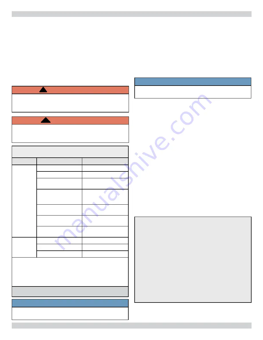
Table 4 - Combustion air and vent pipe fi ttings
must conform with the following:
Item
Material Standards
Vent Pipe
and Fittings
PVC schedule 40
ANSI/ASTM D1785
PVC - DWV
ANSI/ASTM D2665
CPVC schedule 40
ANSI/ASTM D1784/
F441
SDR-21 & SDR-26 PVC
ANSI/ASTM D2241
NOT APPROVED FOR
CANADA
ABS-DWV
ANSI/ASTM D2661
Schedule 40ABS
ANSI/ASTM F628
PP (Polypropylene)
Pipe and Components
UL 1738
ULC S636-08
Pipe
Cement/
Primer
PVC ANSI/ASTM
D2564
CPVC
ANSI/ASTM F493
Schedule 40 ABS
ANSI/ASTM D2235
• IPEX is approved vent manufacturer in Canada listed
to ULC-S636.
• IPEX System 636 Cements and Primers are approved
in Canada listed to ULC-S636.
Use of cellular core PVC (ASTM F891), cellular core CPVC, or Radel
®
,
(Polyphenolsulfone) in venting systems shall be prohibited.
2.
Canadian installations:
• First 3 feet (900mm) of venting must be readily
available for visual inspection.
• Speci
fi
ed primers and glues of certi
fi
ed vent
system must be from single manufacturer, and not
intermixed with other manufacturer’s vent system
parts.
• Components of the certi
fi
ed system must not be
interchanged with other vent systems, or unlisted pipe
and/or
fi
ttings.
NOTICE
Transition from 2” pipe to 3” pipe must be made in
vertical run.
3.
Boiler combustion air and vent piping connections are
sized for 2” pipe. Any pipe size change (to 3”) must be
made outside of boiler casing in vertical run of pipe to
allow for proper drainage of vent condensate. Due to
potential for
fl
ue gas temperatures over 155°F,
fi
rst
fi
ve
(5) feet of vent pipe must be CPVC, the remaining vent
pipe can be PVC. If any elbows are employed within the
fi
rst 5 feet of vent, they must be CPVC also. Two (2) - 30”
pieces of 2” CPVC pipe. 2½” piece of 2” CPVC pipe, a 2”
CPVC elbow and 2” CPVC pipe coupling are furnished with
the boiler. No requirement when using PP pipe.
4.
Combustion air and vent piping lengths. Table 5,
Page 23 .
If vent exceeds 5 ft.
fi
rst 5 ft. of vent piping
run must be 2” CPVC:
Length of pipe is counted from boiler jacket (air
intake pipe) or from vent pipe connector(vent pipe).
Termination is not counted toward the “Total Equivalent
Length”.
For elbows, reduce maximum vent length as shown:
• 2” 90° elbow - 2 ft. per elbow.
• 3” 90° elbow - 3 ft. per elbow.
Example:
To add two (2) 90° elbows to a 3” pipe for a 75 boiler.
Each elbow is 3 ft. per 90° elbow for a total of 6 ft.
(1 elbow @ 3 ft. + 1 elbow @ 3 ft. = 6 equivalent ft. of
pipe)
Total additional pipe is then subtracted from maximum
allowable pipe length to give new maximum length of
112-6=106 ft. with two (2), 90° elbows.
“TOTAL EQUIVALENT LENGTH”:
Original 112 ft. max. - 6 equivalent ft. for 2 elbows =
new 106 ft. maximum length.
COMBUSTION AIR AND VENT PIPE
NOTICE
Use of PP piping, follow manufacture”s installation
instructions and requirements.
Содержание Dunkirk 4 Series
Страница 12: ...12 NEAR BOILER PIPING Figure 2 Single Zone Boiler Piping SAFETY RELIEF VALVE SEE PAGE 18 FOR REQUIREMENTS ...
Страница 15: ...15 NEAR BOILER PIPING Figure 5 Primary Secondary Piping With Circulators And Domestic Hot Water ...
Страница 31: ...31 Figure 20 Field Wiring Connections ELECTRICAL WIRING SAFETY RELIEF VALVE SEE PAGE 18 FOR REQUIREMENTS ...
Страница 33: ...33 Figure 22 Ladder Diagram for Figure 22 ELECTRICAL WIRING ...
Страница 52: ...52 Troubleshooting Chart 1 TROUBLESHOOTING ...
Страница 53: ...53 Troubleshooting Chart 2 TROUBLESHOOTING ...
Страница 63: ...NOTES ...
Страница 64: ...DUNKIRK BOILERS 2201 Dwyer Avenue Utica NY 13501 web site www ecrinternational com ...


