18
Safety Relief Valve
Installation of safety relief valve shall conform to ANSI/
ASME Boiler and Pressure Vessel Code, Section IV.
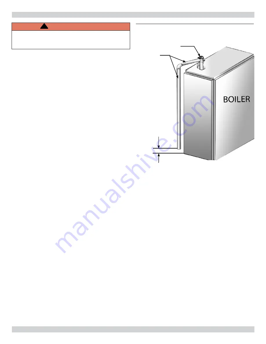
• Install furnished safety relief valve using 3/4” x 4½”
pipe provided with boiler. See Figure 8 .
• Install safety relief valve with spindle in vertical
position.
• Do not install shutoff valve between boiler and safety
relief valve.
• Install discharge piping from safety relief valve. See
Figure 8 .
• Use ¾” or larger pipe.
• Use pipe suitable for temperatures of 375°F (191°C) or
greater.
• Individual boiler discharge piping shall be independent
of other discharge piping.
• Size and arrange discharge piping to avoid reducing
safety relief valve relieving capacity below minimum
relief valve capacity stated on rating plate.
• Run pipe as short and straight as possible to location
protecting user from scalding and properly drain piping.
• Install union, if used, close to safety relief valve outlet.
• Install elbow(s), if used, close to safety relief valve
outlet and downstream of union (if used).
• Terminate pipe with plain end (not threaded).
Expansion Tank And Make-Up Water
Determine required system
fi
ll pressure, system design
temperature, and system water content.
• Boiler contains 2.6 gallons (U.S.). Size expansion tank
accordingly. Consult expansion tank manufacturer for
proper sizing information.
• Connect properly sized expansion tank (not furnished).
Diaphragm type expansion tank see Figure 9, Page 19 .
See Figure 10, Page 20 for conventional closed type
expansion tanks.
• For diaphragm type expansion tanks, adjust tank
air pressure to match system
fi
ll pressure. Install
furnished air vents shown for diaphragm type
expansion tank system only.
• Install make-up water connections as shown per local
codes.
• If pressure reducing valve is used, adjust to match
system
fi
ll pressure.
• Verify clean water supply is available. When water
supply is from well or pump, install sand strainer at
pump
Figure 8 - Relief Valve Boiler Piping
NEAR BOILER PIPING
RELIEF VALVE
DISCHARGE
LINE
Check local
codes for
maximum
distance
from fl oor
or allowable
safe point of
discharge
.
WARNING
Burn and scald hazard. Safety relief valve could
discharge steam or hot water during operation.
Install discharge piping per these instructions.
!
Содержание Dunkirk 4 Series
Страница 12: ...12 NEAR BOILER PIPING Figure 2 Single Zone Boiler Piping SAFETY RELIEF VALVE SEE PAGE 18 FOR REQUIREMENTS ...
Страница 15: ...15 NEAR BOILER PIPING Figure 5 Primary Secondary Piping With Circulators And Domestic Hot Water ...
Страница 31: ...31 Figure 20 Field Wiring Connections ELECTRICAL WIRING SAFETY RELIEF VALVE SEE PAGE 18 FOR REQUIREMENTS ...
Страница 33: ...33 Figure 22 Ladder Diagram for Figure 22 ELECTRICAL WIRING ...
Страница 52: ...52 Troubleshooting Chart 1 TROUBLESHOOTING ...
Страница 53: ...53 Troubleshooting Chart 2 TROUBLESHOOTING ...
Страница 63: ...NOTES ...
Страница 64: ...DUNKIRK BOILERS 2201 Dwyer Avenue Utica NY 13501 web site www ecrinternational com ...


