


Service manual
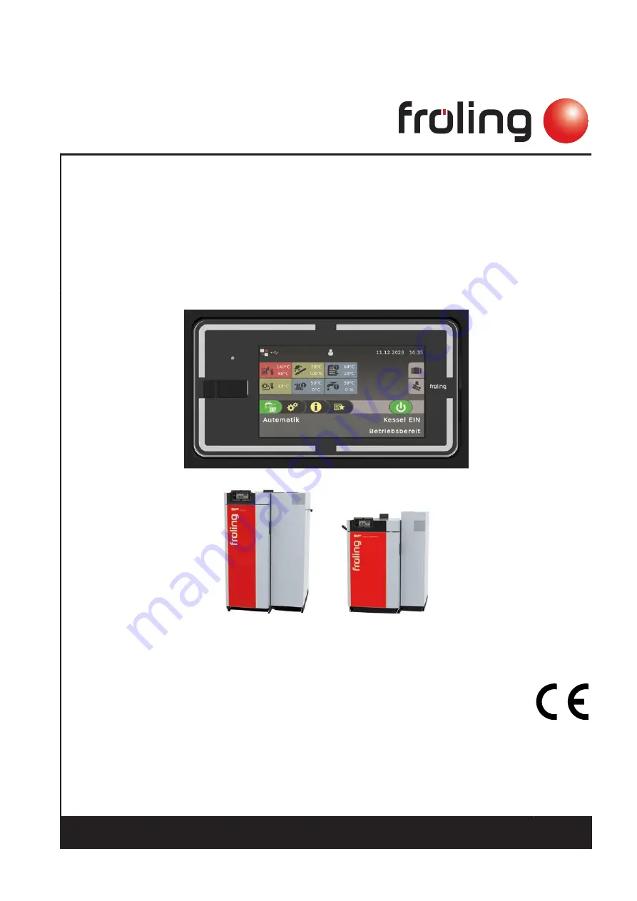
Lambdatronic SP 3200 for dual fuel boiler
Core module version 50.04 - Build 05.18 | Touch control version 60.01 - Build 01.36
Translation of the original German installation instructions for technicians
Read and follow the instructions and safety information!
Technical changes, typographical errors and omissions reserved!
B1460720_en | Edition 30/04/2020
Froling GesmbH | A-4710 Grieskirchen, Industriestraße 12 | www.froeling.com


