3
1
INST
ALLER Section
(en)
7.
press
again to take the boiler to
minimum power
. Wait for the value of
CO
2
to stabilize and then adjust as described in
step 4 of the procedure (power value = 00);
8.
to exit the function, press the buttons for at least 6 seconds as described in step1.
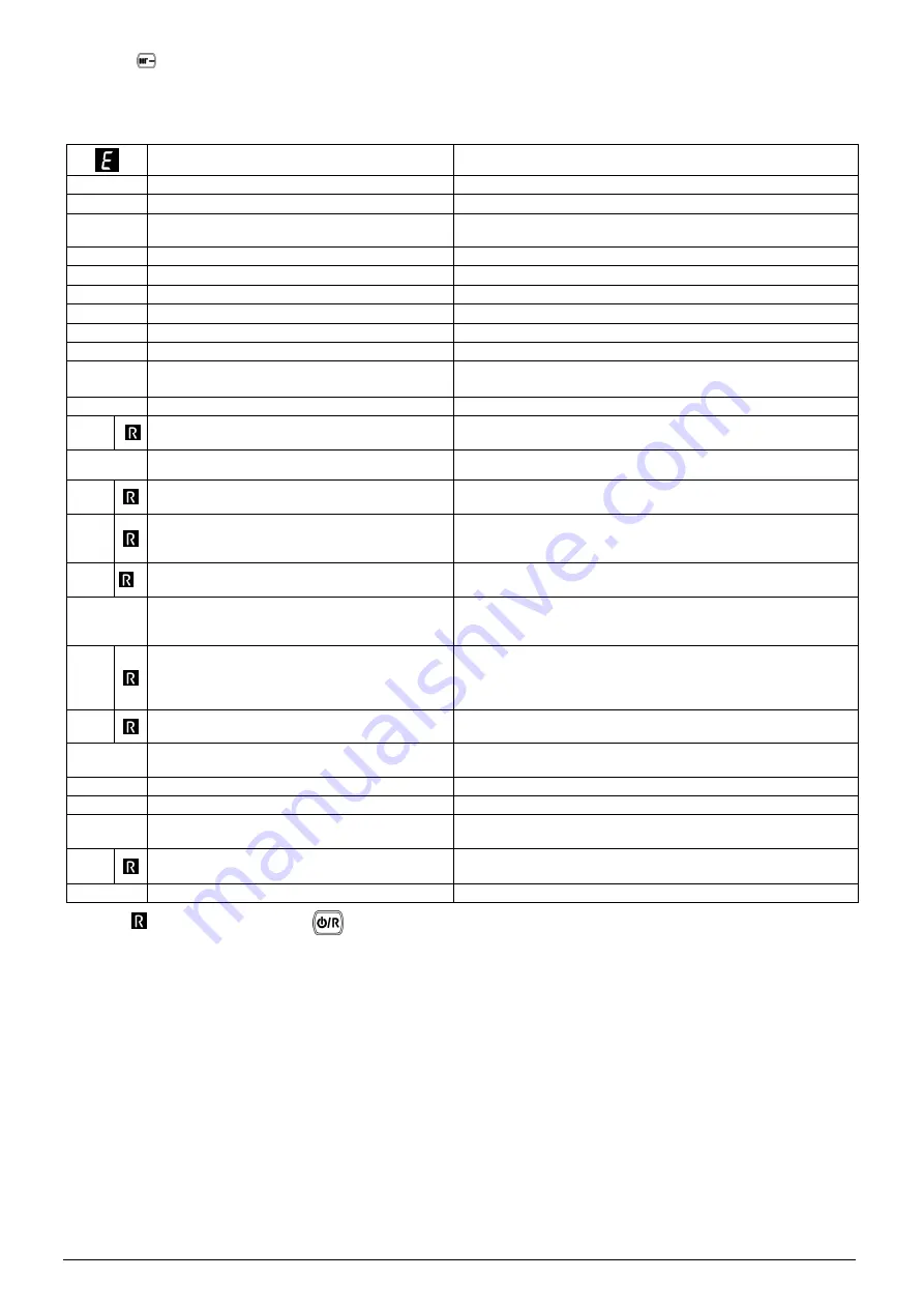
12.5 ERROR MESSAGES AND RESETTING THE BOILER
ERROR description
OPERATION
09
Gas valve connection fault.
Check the cable pcb/gas valve and gas valve plug
10
Outdoor sensor fault .
Check the sensor and the cable
15
Gas valve command fault.
Verify all the cables. Replace the pcb.
Call an authorized SERVICE center
20
Central Heating NTC sensor fault.
Check the sensor and the cable
28
Flue NTC heat exchanger sensor fault
Check the sensor and the cable
40
Return NTC sensor fault.
Check the sensor and the cable
50
Domestic Hot Water NTC sensor fault
Check the sensor and the cable
53
Obstruction in the flue pipe.
Check obstruction on the flue pipe
55
PCB not programmed.
Call an authorized SERVICE centre
83-84-85
86-87
Communication problem between boiler board and
control unit.
Probable short circuit on wiring.
Check the cable between control unit and boiler
109
Pre-circulation alarm (temporary fault).
Check the correct circulation of the water and the pump
110
Safety thermostat tripped due to over temperature
(pump probably blocked or air in heating circuit).
Check the safety thermostat and the cable; check the correct circulation
of the water and the pump
118
Hydraulic pressure too low.
Refill the heating system by open the cold water tap
125
No circulation of the water
(control performed via a temperature sensor).
Check the correct circulation of the water and the pump.
Check the correct connection of the NTC sensor on the pipe
128
Loss of flame.
Check the sensing electrode and the cable, flue recirculation, electrical
continuity between burner and ground, Enable the automatic calibration.
Call an authorized SERVICE centre
130
NTC flue sensor tripped due to over temperature.
Check the thermostat, the correct circulation of the water and the pump.
Check the status of the primary exchanger
131
Thermo fuse tripped due to over temperature.
Check the thermo fuse, the correct circulation of the water and the
pump. Check the status of the primary exchanger. Replace the heat
exchanger.
Call an authorized SERVICE center
133
Ignition failure
Check the correct operation of the condensate trap. Check the sensing
electrode, spark electrode and cable. Check flue recirculation,
electrical
continuity between burner and ground.
Enable the automatic calibration
function.
Call an authorized SERVICE centre
134
Gas supply valve blocked.
Check the gas pressure, sensing electrode, spark electrode and cable,
replace the pcb if it necessary.
Call an authorized SERVICE center
135
Internal error.
Verify all the cables. Replace the pcb.
Call an authorized SERVICE center
160
Fan fault.
Check the fan and the cable
162/317
Incorrect power supply frequency.
Incorrect power supply frequency.
169
Flue pressure switch (contact open)
Check the pressure switch and the cable.
Check obstruction on the flue pipe
164/
384
Fault flame (parasitic flame).
Check the correct operation of the gas valve.
165/385
Input voltage too low.
Check the power supply
for at least 2 seconds. For other error codes not described in the table please contact
To RESET
the boiler press the button
Utica Boiler
at 1(800)
325
-
5479
.
2400
11317
,
REV
D
(
0
7
/
30
/1
6
)
Содержание UTICA BOILERS MAC-150
Страница 10: ...MAC 150 Low Water Pressure Cutoff 10 240011317 REV D 07 30 16...
Страница 11: ...MAH 125 Low Water Pressure Cutoff 11 240011317 REV D 07 30 16...
Страница 54: ...Coupure de la pression d eau faible 54 240011317 REV D 07 30 16...
Страница 84: ...84 S e c t i o n I N S T A L L A T E U R f r 240011317 REV D 07 30 16...
Страница 87: ...87 S e c t i o n I N S T A L L A T E U R f r 240011317 REV D 07 30 16...


