41
DIAGNOSTICS
This feature allows a service technician to check the
operating state of individual components in the condi-
tioner/refiner (e.g. valve position) to troubleshoot prob-
lems.
If an error code is displayed in place of the
rolling status screens, call your dealer for service.
To view the Diagnostics screen:
1
. If an error code is displayed, skip Steps 2-7 and go
directly to Step 8.
2
. To display the Diagnostics screen from any of the
rolling status screens (when an error code is not dis-
played), press the SELECT (
¡
) button to display the
Main menu
.
3
. Press the DOWN (
6
) button to scroll through the
menu options until
Advanced settings
is highlighted.
4
. Press the SELECT (
¡
) button to display the
Advanced settings menu.
5
. Press the DOWN (
6
) button to scroll through the
menu options until
Troubleshooting
is highlighted.
6
. Press the SELECT (
¡
) button to display the
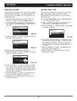
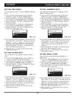
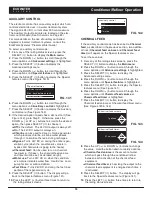
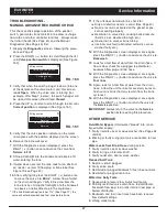
Troubleshooting menu (See Figure 150).
Diagnostics
Setup changes
SLS calibration
Troubleshooting
FIG. 150
7
. Make sure
Diagnostics
is highlighted.
8
. Press the SELECT (
¡
) button to display the
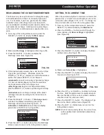
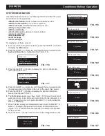
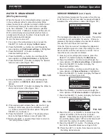
Diagnostics screen (See Figure 151).
Diagnostics
Time:
3:45 PM
Position time:
0:00
FIG. 151
9
. Press the DOWN (
6
) or UP (
5
) buttons to scroll
through the list. The following items are displayed:
=
Time
(current)
=
Position time
(counts down the time remaining in
the current valve position)
=
Current position
(of the valve: service, fill, brine,
backwash, fast rinse or moving)
=
Requested position
(of the valve)
=
Motor state
(on or off)
=
Valve position switch
(open or closed)
=
Turbine count
(if changing, indicates water flow)
=
Salt level sensor
(distance reading of sensor)
=
Drain TDS
(total dissolved solids in ppm)
=
Drain temperature
(°C)
=
Tank light switch
(open or closed)
=
RF module
(detected or not)
=
Error code
(call for service if a number is displayed)
10
. When finished viewing the Diagnostics screen,
press the SELECT (
¡
) button. The display will go
back to the Troubleshooting menu.
11
. Press the LEFT (
3
) button three times to return to
the rolling status screens (or error code screen if an
error condition exists).
SETUP CHANGES
This feature allows a service technician to repeat the
setup procedure (See Pages 13-15 or 17) or restore the
conditioner/refiner’s default operating values.
1
. From any of the rolling status screens, press the
SELECT (
¡
) button to display the
Main menu
.
2
. Press the DOWN (
6
) button to scroll through the
menu options until
Advanced settings
is highlighted.
3
. Press the SELECT (
¡
) button to display the
Advanced settings menu.
4
. Press the DOWN (
6
) button to scroll through the
menu options until
Troubleshooting
is highlighted.
5
. Press the SELECT (
¡
) button to display the
Troubleshooting menu (See Figure 150).
6
. Press the DOWN (
6
) button to scroll through the
menu options until
Setup changes
is highlighted.
7
. Press the SELECT (
¡
) button to display the Setup
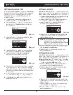
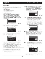
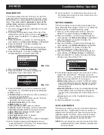
changes menu (See Figure 152).
Redo setup
Restore defaults
Cancel
Setup changes
FIG. 152
8
. If the desired option already has a dot next to it (See
Figure 152), go to Step 9. Otherwise, press the
DOWN (
6
) or UP (
5
) buttons to scroll to the desired
option, then press SELECT (
¡
) to choose it.
=
Redo setup
allows you to select a different model
code (intended to be used for upgrades or retrofits
of existing conditioner/refiners). Model codes are
listed on Page 5.
=
Restore defaults
will reset all customizable settings
to their default values and take you through the
“wizard” screen setup procedure (See Pages 13-15
or 17).
=
Cancel
will return to the Troubleshooting menu
(Figure 150).
9
. Press the SELECT (
¡
) button.
SLS CALIBRATION
This feature is used by a service technician replacing a
salt level sensor. A replacement salt level sensor is
shipped from the factory with numerical values for two
calibration points, and these values must be entered
into the controller. Instructions for this procedure are
supplied with the replacement salt level sensor.
NOTE:
Do not change the numerical values of the SLS
calibration points unless installing a replacement
salt level sensor.
ECOWATER
S Y S T E M S
Conditioner/Refiner Operation
Содержание ECR3700R20
Страница 49: ...49 ECOWATER S Y S T E M S Notes ...

