STIEBEL ELTRON IS E, Service Manual
Get ready for seamless operation of your Stiebel Eltron IS E with our free Service Manual download. This comprehensive manual provides detailed instructions on installation, operation, and troubleshooting. Ensure optimal performance by downloading the manual from our website manualshive.com today.
Share
Download


Reviews:
No comments
Related manuals for IS E

D55
Brand: Water Well Pages: 5

CX Series
Brand: Waterous Pages: 13

CX Series
Brand: Waterous Pages: 8

521
Brand: Zilmet Pages: 10

S series
Brand: salmson Pages: 49

TVC Series
Brand: Gabarron Pages: 8

Tornado
Brand: KEKAI Pages: 12

Flat
Brand: Warmhaus Pages: 8
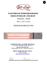
PEGASUS
Brand: Jet-Line Pages: 22

Delta Solo Compact MVP Series
Brand: KSB Pages: 40

RJS-75SS Series
Brand: red lion Pages: 32

UVHB20
Brand: pyromaster Pages: 16

MagicComfort MSH 300
Brand: Waeco Pages: 192

OKC 300 NTR/HP
Brand: Drazice Pages: 9

Akva Les II S
Brand: Danfoss Pages: 28

AXESS 180
Brand: salmson Pages: 16

Aqua Dual Mate ADM Series
Brand: ChemChek Pages: 2

VM024LP
Brand: Sure Heat Pages: 12


