Econo-Wrap EW-1800T Скачать руководство пользователя страница 49

Self

-

loading Bale Wrapper EW

-

1800T


49


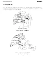
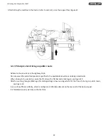
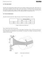
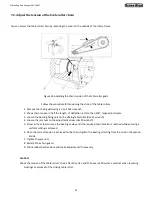
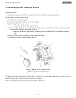
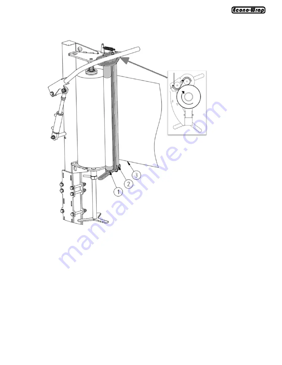
Figure 32 Film threading direction


(1) roller I, (2) roller II, (3) film 


Threading the film must follow the direction shown in Figure 31. When mounted correctly, the film (3) is unwound to be 
wrapped around roller I (1) first, and then routed behind roller II (2) and tied on the first bale to be wrapped.
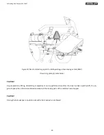
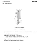
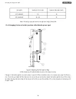
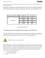
 

For installing the 

30” 

wide film you need to adjust the film dispenser to this type of rolls. The use of the wider film requires 

changing the gear ratio of the turntable. For details, refer to Section 7.5.


Содержание EW-1800T

Страница 1: ...Rel 06 07 21 Self loading Bale Wrapper EW 1800T Operator s Manual...

Страница 2: ...Self loading Bale Wrapper EW 1800T 2 Page left blank intentionally...

Страница 3: ...irs Service The repair performance date is included in the WARRANTY CERTIFICATE Machine parts and components which are subject to wear in normal operating conditions are not covered by the warranty re...

Страница 4: ...ydraulic system 34 6 Machine operation 35 6 1 Installing the bale wrapper 36 6 2 Connecting bale wrapper to a tractor 36 6 3 Levelling the bale wrapper 37 6 4 Transport position 38 6 4 1 Principles fo...

Страница 5: ...teel rims 61 8 Control system 62 8 1 Control unit 62 8 1 1 Description of functions of the control unit 63 8 2 Operating modes 65 8 3 Control panel operation 66 8 3 1 AUTO mode 66 8 3 2 SEMI AUTO mode...

Страница 6: ...12 12 Rotary base set 103 12 13 Drive assembly 104 12 15 Chain guard 105 12 14 Rotary frame set 106 12 16 Film cut and hold set 108 12 17 Dispenser post set 110 12 18 Film dispenser set 112 12 19 Disp...

Страница 7: ...r avoid risks This manual also contains principles of correct use of the machine and specifies the maintenance jobs to be carried out If you do not understand any information contained herein please c...

Страница 8: ...ate containing the most important identification data The plate is affixed on the front beam of the machine bottom frame Figure 1 Rating plate The rating plate includes full name of the manufacturer b...

Страница 9: ...on 3 1 User safety The self loading bale wrapper can only be operated by adults who have learned how to operate it and have read this In structions Manual as well as have appropriate qualifications Th...

Страница 10: ...be provided with the complete first aid kit with instructions of use Before starting work the bale wrapper must be set in the transport position Take special care when driving on public roads and comp...

Страница 11: ...over and transporting the machine inspect its technical condition to check for damage Standing under the raised grab arm is not allowed to prevent being crushed by the components of the machine When a...

Страница 12: ...or example the inability to completely cover the ma chine s working unit certain risk factors may occur No Risk Risk source cause Protection measures against risks 1 Overloading the lo comotor system...

Страница 13: ...uctions 9 Noise Too high rotational speed of the machine damaged loose or vi brating parts Operation of the machine in good technical con dition inspections on a regular basis proper rotational speed...

Страница 14: ...before any maintenance or repair pro cedures 1 3 Danger of limb injuries Do not reach for the cutting blade 1 4 Maintain a distance of at least 50 metres 164 feet from the working machine 1 5 Danger o...

Страница 15: ...ds flowing under pressure Read the Instructions Manual and learn about the maintenance works 1 9 Wrapping film installation method 1 10 Direction of table rotation 1 11 Lifting hook location dur 1 12...

Страница 16: ...ning about pressure present in the hydraulic system 1 16 Use a protective coverall 1 17 Use safety gloves 1 18 Use a protective helmet 1 19 Use hearing protectors 1 20 Use safety glasses Table 2 Safet...

Страница 17: ...Self loading Bale Wrapper EW 1800T 17 Table 2 cont Safety decals on the machine...

Страница 18: ...Self loading Bale Wrapper EW 1800T 18 Table 2 cont Safety decals on the machine...

Страница 19: ...eed 3 mph provided that the ride takes place on flat level ground Accident prevention regula tions and all basic rules of safety and hygiene as well as traffic regulations must always be observed Inte...

Страница 20: ...le around its two axes of rotation The turntable slide base underneath the rotary frame pinned to the bottom frame is to unload bales by a hinged tilt to the rear of the machine where the bale tipper...

Страница 21: ...Technical specification The main components of the bale wrapper are shown in the figure below 1 Bottom frame 2 Turntable slide base 3 Film cut and hold 4 Rotary frame 5 Dispenser post 6 Film dispenser...

Страница 22: ...b 2425 8 Permissible speed of the turntable rpm 30 9 Required tractor power HP 48 10 Hydraulic motor oil demand min max l min 14 5 23 11 System max pressure psi 2320 12 Hydraulic sockets As per ISO 74...

Страница 23: ...film which one after the other are rolled out from the film dispenser 5 This unit is placed on a rotary frame 3 driven by a chain drive to rotate the bale After the wrapping is complete the rotary fr...

Страница 24: ...tuator The dispenser is adapted for film with a width of 20 or 30 It is installed on the dispenser post 7 and adjusted with screw with handle 8 The film roll is mounted between the conical holders 3 a...

Страница 25: ...ntal movement of bales is also achieved thanks to the rotation of the table through a bevel gear mounted in its central part connected by a shaft with the chain drive 1 which transmits the drive to th...

Страница 26: ...ted when the bale is unloaded from the rotary frame moves the cradle frame The foot plate 4 is lowered which is caused by the unloading movement of the rotary frame and the movement of the bumper moun...

Страница 27: ...tal tipping B set for vertical tipping For a description of how to change the bale tipper settings see Section 6 5 It is important that the unloading movement from the tipper is as smooth as possible...

Страница 28: ...oller on the frame 1 screwed to the profile of the rotary frame The film is cut and held in place by the automatically controlled hydraulic system The piston in the actuator 7 is pushed out by means o...

Страница 29: ...ct with sharp edges of the blade 1 by using the guard 2 The guard 2 is removed and replaced by fixing the guard 2 to the plate 4 using the screws 3 Any preparations fitting dismantling or adjustment c...

Страница 30: ...mp 2 warning plate reflective triangle The electrical system of the bale wrapper is designed to be powered from a 12 V DC source The electrical system of the bale wrapper s lights should be connected...

Страница 31: ...right multifunction tail lamp LL left multifunction tail lamp Designation Function 31 Ground Power supply 12 V L Left direction indicator 54 Brake light 58L Tail light left 58R Tail light right R Righ...

Страница 32: ...position C2 Bale lift top position C3 Bale loading position C4 Bale unloading position C5 Table tilt C6 Bale tipper table bottom position 1A 1B Solenoid valves for bale lift actuator 2A 2B Solenoid va...

Страница 33: ...lf loading Bale Wrapper EW 1800T 33 Figure 16 Positions of sensors in the frame It is forbidden to work with sensors switched off or damaged as their proper functioning protects the machine from damag...

Страница 34: ...in packaging adapted to their storage paying partic ular attention to the effect of hydrocarbons SECTION III SECTION II SECTION I SECTION IV SECTION I By controlling the pressure on Section I used for...

Страница 35: ...ed Table check the condition and pressure of tires check the appropriateness of wheel mounting check the painting coating condition check the overall condition of the machine with regard to any damage...

Страница 36: ...pper in reverse gear slowly backup to the bale wrapper s hitch 1 ensuring that nobody is standing between the machine and the tractor or in the immediate vicinity of the machine when backing up move t...

Страница 37: ...n 2 drawbar 3 sleeves The machine must be levelled before it is coupled with the tractor When setting the machine horizontally pay particular attention to the position of the drawbar hitch and if nece...

Страница 38: ...arting work in the field re move the locking flat bar 3 from the bale lift Figure 20 by removing the locking pin 2 from the pin 1 to remove the flat bar and put it securely in the working position Fig...

Страница 39: ...e secure the lift arm with a flat bar and a locking pin see Figure 20 Attach a warning triangle SMV sign for distinguishing a slow running vehicle for the time of driving on public roads see Figure 23...

Страница 40: ...ng plate 2 plate holder Caution Any preparations fitting dismantling or adjustment can be performed only after the drive has been switched off the en gine stopped the vehicle immobilised and when all...

Страница 41: ...behind the machine while the second one involves standing the bale vertically on its bottom to the tipper s left The way to unload is switched over by selecting the position of the adjustable arm 1 Ro...

Страница 42: ...table arm the cradle frame needs to be lifted and the adjustment pin removed Figure 26 Bale lift arm adjustment 1 frame 2 buffer 3 adjustable arm 4 lock screw 5 buffer fixing Customise the bale lift a...

Страница 43: ...red position 7 Re install and tighten the buffer mounting bolts When moving the bale wrapper for bale lift adjustment ensure no unauthorised persons stand in the immedi ate area surrounding the machin...

Страница 44: ...he film tension Section 6 7 1 and make adjustments if necessary Section 6 7 2 6 7 1 Correct film tension The width of the film measured at the edge of the bale must be within the range shown in Table...

Страница 45: ...on should increase The correct distance between lines at the 55 70 film pre tension must be be tween 6 00 and 6 50 Figure 28 Tension check method two Caution The dimensions of the film are approximate...

Страница 46: ...film tension by ways described in Section 6 6 1 1 Loosen the jam nut 2 on the pressure screw 1 2 Adjust the screw pressure by checking the film resistance 3 If the film tension is too high lower the...

Страница 47: ...ght The optimised dispenser position is when the centre of the film is at the same height as the cen tre of the bale To adjust the height of the dispenser use the dispenser post turn lever 1 to move t...

Страница 48: ...the jam nut 2 Lower the lower holder cone 4 by removing the pressure screw 3 Position the film roll onto the holder cones 4 and 5 starting from the upper cone 5 The roll must be aligned with the cone...

Страница 49: ...31 When mounted correctly the film 3 is unwound to be wrapped around roller I 1 first and then routed behind roller II 2 and tied on the first bale to be wrapped For installing the 30 wide film you n...

Страница 50: ...and securing the actuator of the turntable slide base Figure 33 Locking the rotary frame Caution All maintenance works must be carried out with the rotary frame locked with a rod Turn off the engine...

Страница 51: ...alue in the range of 3 to 5 mm 4 Fix the motor plate 2 5 Fold the protection rod and lower the table 6 Carry out the test start of table rotation Note that the table movement should be smooth without...

Страница 52: ...the bearing fixing nuts on the driving table roller size 21 wrench 4 Loosen the jam nuts on the adjustment screw size 19 wrench 5 Screw in the screw to move the bearings away until the required chain...

Страница 53: ...of the cradle drop of the tipper The bale tipper is lifted at a constant speed and the speed does not depend on the controller setting Turn to the right to reduce the speed of the drop Turn to the lef...

Страница 54: ...l to each other which extends the life of the belts If the distances L1 and L2 are different the bearing position must be readjusted 6 The adjustment of the driving table roller must be carried out in...

Страница 55: ...See Table 7 on page 56 If the sprocket needs to be changed proceed with the following If the sprocket does not need to be changed check the chain tension and attach the guard 4 Loosen the bearing fix...

Страница 56: ...ure 39 Adjusting the film height settings 1 film dispenser 2 bottom holder 3 jam nut 4 pressure screw Changes in the holder position are made when a new roll of film is installed or when it is necessa...

Страница 57: ...works The User s responsibility is to Monitor air pressure Assess the technical condition of the wheels and tires Ensure the wheels are tightened properly Check the running axle bearings for play and...

Страница 58: ...heel with its other end resting on the ground A damaged or missing hub cap will let dirt and moisture penetrate the hub resulting in much faster wear of bear ings and hub seals Bearing service life de...

Страница 59: ...groove of the nut with the hole in the running axle stud The wheel should turn without any excessive resistance The nut must not be over tightened Over tightening is not recommended due to the worse...

Страница 60: ...hub Lower the bale wrapper tighten the nuts according to the recommended torque and the order shown in Figure 42 Tightening the nuts Figure 42 Nut tightening order 1 6 nut tightening order L length o...

Страница 61: ...le wrapper must be unloaded at such time The check should be carried out before driving when the tires are not warmed up or after a prolonged standstill Damaged tires or rims can cause a serious accid...

Страница 62: ...to be plugged into the box located on the bale wrap per as per the procedure in Figure 15 and Section 5 3 5 The next step is to connect the power cable of the control unit to the tractor power supply...

Страница 63: ...of the control unit NO KEY DESCRIPTION 1 Confirms selection 2 Cancels selection and exits the selected screen 3 Moves cursor up 4 Moves cursor down Inserts a dot 5 Moves cursor left 6 Moves cursor ri...

Страница 64: ...frame in the opposite direction Enters 7 11 Tilts the table bale unloading Enters 3 12 Lowers the table Enters 8 13 Cuts and holds the film Enters 4 14 Releases the film Enters 9 15 Goes to the menu...

Страница 65: ...t until the button is released The operation is terminated at any time after removing the finger from the button MANUAL Mode In the MANUAL mode all operations are confirmed by the operator who holds d...

Страница 66: ...htly Automatic mode screen Semi Auto mode screen Resuming the operation of the section after the stopping Semi Auto Moving the rotary frame to the next sen sor position 8 3 1 AUTO mode Select the AUTO...

Страница 67: ...ess the screen key to change the number of turns setting The execution of the individual operations depends on protections the function of which is performed by the sensors If executing an action is n...

Страница 68: ...the button is released The operation is terminated at any time after removing the finger from the button In order to facilitate the work for the operator the screen comes with a positioning key Select...

Страница 69: ...reen key and then use the keys to move the cursor and select the desired speed to confirm touch The selection of the setpoint speed applies to all sections altogether 8 4 Menu By selecting on the pane...

Страница 70: ...move to the menu by pressing and highlight the cursor by pressing use arrows to select the Operating Mode item and touch to confirm 8 4 2 Changing the bale weight To change the bale weight move to the...

Страница 71: ...ics To view or restart the Statistics move to the menu by pressing and highlight the cursor by pressing use arrows to select the Status item and touch to confirm The information in statistics may be r...

Страница 72: ...mpleted on a given day and all the cycles the machine has ever completed After selecting the restart only the day s count of cycles can be reset Confirm the restart with the key on the screen Cycle ti...

Страница 73: ...me left before inspection An approximate time before the next machine inspection is also given Carrying out the inspection will require the timer to be restarted for the next inspection Confirming the...

Страница 74: ...ettings Changing the speed in AUTO and Auto Manual modes to custom settings requires a password Entering a password and confirming involves the risk of exceeding the safe operating speed of the machin...

Страница 75: ...gin and the contact telephone 8 7 Date and time settings To set the date and time move to the menu by pressing and highlight the cursor by pressing use arrows to select the Time Date item and touch to...

Страница 76: ...with 8 9 Application update To make an update move to the menu by pressing and highlight the cursor by pressing use arrows to select the Update item and touch to confirm The screen will prompt you to...

Страница 77: ...fting time exceeded No info on whether the lift is lowered No item to unload found No signal from the load sensor No info on the rising action of the table tilt No info on the lowering action of the t...

Страница 78: ...d remove any found damage or replace a worn element with a new one In case of varnish coating damage remove any mechanical residues of an old painting degrease and then apply a primer coat When the pr...

Страница 79: ...se should be removed in order to limit dirt adherence All maintenance works should be done with the switched off engine of the vehicle released pres sure and stopped rotations and with both the vehicl...

Страница 80: ...ne grease for chain drives 2 Table roller drive gear Pre seasonally every 30 hours of work or 1x a year Machine grease for chain drives 3 Film dispenser gears Pre seasonally every 30 hours of work or...

Страница 81: ...a year Machine grease for heavy duty compo nents 8 Tilt actuator Pre seasonally every 10 hours of work or 1x a year Machine grease 9 Table roller bear ings Pre seasonally every 10 hours of work or 1x...

Страница 82: ...a year Machine grease 14 Support foot Pre seasonally every 30 hours of work or 1x a year Machine grease 15 Hitch Pre seasonally every 10 hours of work or 1x a year Machine grease 16 Bumper pin Pre sea...

Страница 83: ...winter it is recommended to Lubricate any moving joints with fresh grease Apply commercially available anti corrosion silicone based agents on the surface of bolts and pins to inhibit the corro sion o...

Страница 84: ...es not return from the actuators Hydraulic pump delivery flow rate of the tractor too high Reduce the delivery flow rate Hose blockage Check the hoses for kinks or damage Replace if necessary Actuator...

Страница 85: ...ed during wrapping Bale wrapping asymmetrical Incorrect dispenser height Adjust the height of the film dispenser to suit the bale size The bale falls off the machine during wrapping Rotational speed t...

Страница 86: ...through out the period of use of the machine as oil may pollute the environment Protect your hands and body against injuries and the harmful effects of lubricants and oils Use personal equipment meas...

Страница 87: ...y prior agreement with the manufacturer Table 12 presents additional equipment Table 12 Refitting options for the premium version EQUIPMENT VERSION STANDARD PREMIUM Additional film dispenser NO YES Wo...

Страница 88: ...dered Spare parts must be ordered at the points of sale of the machines or from the manufacturer Use only the original spare parts provided by the manufacturer to guarantee safe and reliable operation...

Страница 89: ...89 Rel 06 07 21 Self loading Bale Wrapper EW 1800T Parts Manual 89...

Страница 90: ...Self loading Bale Wrapper EW 1800T 90 Page left blank intentionally...

Страница 91: ...rt Description Qty 1 TW18001 Bottom frame set 1 2 TW18002 Turntable slide base 1 3 TW18003 Rotary frame set 1 4 TW18004 Film cut and hold 1 5 TW18005 Dispenser post 1 6 TW18006 Film dispenser 1 7 TW18...

Страница 92: ...Self loading Bale Wrapper EW 1800T 92 12 2 Bottom frame set...

Страница 93: ...11 TW18020 Lift actuator pin 1 12 TW18021 Bale lift pin 2 13 GN061S Straight grease nipple M6x1 2 14 TW18166 Spring type straight pin fi6x45 St 4 15 TW18022 Slide base pin 2 16 TW18023 Vibration damp...

Страница 94: ...loading Bale Wrapper EW 1800T 94 12 3 Drawbar set Item Part Description Qty 1 TW18011 Drawbar set 1 2 EP302 0204 Nut HH M16 8 galv self lock 10 3 FW16 Washer 16 galv 20 4 TW18183 Bolt HH M16x50 8 8 ga...

Страница 95: ...TW18028 Hitch eye optional 1 3 FW16 Washer 16 galv 8 4 TW18184 Hex Bolt M16x170 8 8 galv 2 5 TW18029 Hitch fixing spacer 2 6 LNM1620 Self locking nut M16 4 7 TW18185 Bolt HH M16x50 8 8 galv 2 Note It...

Страница 96: ...Self loading Bale Wrapper EW 1800T 96 12 5 Counterweight set Item Part Description Qty 1 TW18013 Counterweight 1 2 TW18030 Lid 1 3 TW18186 Round head bolt M6x10 galv 4 4 EP303 0158 Lock wash 6 galv 4...

Страница 97: ...loading Bale Wrapper EW 1800T 97 12 6 Foot support set Item Part Description Qty 1 TW18014 Support foot 1 2 TW18187 Bolt HH M12x40 8 8 galv 4 3 EP302 0304 Nut HH M12 8 GAL self cl 4 4 LW12 Washer 12 g...

Страница 98: ...Self loading Bale Wrapper EW 1800T 98 12 7 Safety arm set Item Part Description Qty 1 TW18015 Safety arm 1 2 TW18188 Hex nut M14 8 galv self lock 1 3 TW18031 Chain 1 4 TW18189 Double locking pin 1...

Страница 99: ...T 99 12 8 Manifold fixing set Item Part Description Qty 1 TW18016 Manifold mount 1 2 TW18032 Grommet 2 3 FW10 Washer 10 galv 1 4 TW18190 Bolt HH M10x25 8 8 galv 3 5 EP302 0328 Nut HH M10 8 GAL self cl...

Страница 100: ...Bale Wrapper EW 1800T 100 12 9 Film storage set Item Part Description Qty 1 TW18017 Film storage 1 2 TW18032 Pipe caps 3 3 TW18191 Bolt HH M8x25 8 8 GAL 1 4 FW08 Washer 8 galv 2 5 EP302 0209 Self lock...

Страница 101: ...f loading Bale Wrapper EW 1800T 101 12 10 Platform set Item Part Description Qty 1 TW18019 Platform 1 2 TW18192 Round head bolt M8x25 galv 9 3 FW08 Washer 8 galv 18 4 EP302 0209 Nut M8 galv self lock...

Страница 102: ...k washer 8 2 8 TW18038 Slide sensor position plate 1 9 EP302 0203 Self locking nut M10 2 10 FW10 Washer 10 2 11 TW18039 Bumper 2 12 FW20 Washer 20 4 13 BM2025150 Bolt M20x150 np gw 1 14 TW18040 Slide...

Страница 103: ...TW18045 Hub rotary base 1 3 TW18197 Grease nipple M10x1 1 4 TW18198 Bearing 2 5 FW12 Washer mb12 1 6 TW18199 Shim 30 7 TW18200 Nut KM12 1 8 TW18046 Conical gear 1 9 FW25 Washer 25 1 10 TW18201 Nut M24...

Страница 104: ...M080732 Key 8x7x32 1 5 TW18050 Washer special 1 6 LFW08 Lock washer 8 1 7 TW18191 Bolt M8x25 1 8 TW18204 Bolt M12x45 2 9 FW12 Washer 12 2 10 EP302 0204 Self locking nut M16 5 11 FW16 Washer 16 10 12 T...

Страница 105: ...elf loading Bale Wrapper EW 1800T 105 12 14 Chain guard Item Part Description Qty 1 TW18053 Guard rear wall 1 2 TW18054 Chain guard 1 3 FW06 Washer 6 10 4 LFW06 Lock washer 6 10 5 TW18218 Bolt M6x16 1...

Страница 106: ...Self loading Bale Wrapper EW 1800T 106 12 15 Rotary frame set...

Страница 107: ...5 KM080732 Key 8x7x32 1 16 TW18061 Spacer sleeve KS 1 17 TW18211 Circlip Z30 3 18 TW18212 Carriage bolt M12x35 4 19 TW18062 Frame rotation chain guard 1 20 EP302 0203 Nut M10 self locking 12 21 FW10 W...

Страница 108: ...Self loading Bale Wrapper EW 1800T 108 12 16 Film cut and hold set...

Страница 109: ...elf locking nut M16 7 9 EP302 0202 Self locking nut M12 4 10 TW18221 Bolt M16x80 np gw 1 11 TW18222 Film cut and hold complete actuator 1 12 TW18069 Guide sliding sleeve 1 13 TW18211 Circlip Z30 1 14...

Страница 110: ...Self loading Bale Wrapper EW 1800T 110 12 17 Dispenser post set...

Страница 111: ...05 Arm upper bolt 1 12 FW16 Washer 16 20 13 TW18234 Bolt M16x230 np gw 1 14 LNM1620 Self locking nut M16 12 15 TW18235 Film scraper actuator 1 16 TW18078 Spring washer 50 1 17 TW18236 Corner closing s...

Страница 112: ...8086 Dispenser rack 1 2 TW18087 Dispenser roller No 2 1 3 TW18088 Gear cover 1 4 TW18239 spring 5223 89 036 0 2 5 TW18240 Bolt M6x45 2 6 EP302 0304 Nut M12 6 7 FW12 Washer 12 9 8 TW18141 Bolt M12x35 1...

Страница 113: ...pper EW 1800T 113 12 19 Dispenser roller No 1 Item Part Description Qty 1 TW18090 Dispenser roller 1 2 TW18091 Gear wheel large 1 3 LFW06 Lock washer 6 1 4 TW18218 Bolt M6x16 2 5 TW18244 Bearing 2 6 T...

Страница 114: ...per EW 1800T 114 12 20 Dispenser roller No 2 Item Part Description Qty 1 TW18090 Dispenser roller 1 2 TW18092 Gear wheel small 1 3 LFW06 Lock washer 6 1 4 TW18243 Bolt M6x16 2 5 TW18240 Bolt M6x45 2 6...

Страница 115: ...Self loading Bale Wrapper EW 1800T 115 12 21 Table rollers Item Part Description Qty 1 TW18093 Idle table roller set 1 2 TW18094 Driving table roller set 1 3 TW18095 Rubber belt conveyor belt 4...

Страница 116: ...g Bale Wrapper EW 1800T 116 12 22 Idle table roller set Item Part Description Qty 1 TW18096 Idle table roller 1 2 TW18246 Table roller bearing 2 3 FW14 Washer 14 4 4 LFW14 Lock washer 14 4 5 TW18247 B...

Страница 117: ...46 Table roller bearing 2 3 TW18098 Hub 1 4 TW18099 Gear wheel 3 4 Z21 1 5 TW18248 Bolt M8x35 1 6 TW18249 Key 10x8x28 1 7 EP302 0209 Self locking nut M8 1 8 TW18247 Bolt 14x30 4 9 LFW14 Lock washer 14...

Страница 118: ...arm 1 3 TW18103 Buffer 1 4 TW18242 Bolt M12x40 4 5 EP302 0202 Self locking nut M12 4 6 FW12 Washer 12 8 7 TW18250 Self locking nut M24 1 8 FW25 Washer 25 2 9 TW18251 Locking pin 6 0 27 32 2 10 TW18104...

Страница 119: ...W18254 Spring type straight pin 6x45 2 6 TW18205 Bolt M16x45 4 7 FW16 Washer 16 8 8 TW18110 Actuator pin short 1 9 LNM1620 Nut M16 4 10 TW18111 Bale tipper resistance 1 11 TW18112 Bale tipper actuator...

Страница 120: ...r 1 5 EP302 0201 Nut M 10 self locking 3 6 FW10 Washer 10 4 7 TW18120 Cradle pin 1 8 TW18257 Bolt M10x30 1 9 TW18121 Vibration damper 50x21 D 2 10 TW18122 Tension spring fi6xfi60x250_r 1 11 TW18123 Sp...

Страница 121: ...f loading Bale Wrapper EW 1800T 121 12 27 Adjustable arm set Item Part Description Qty 1 TW18125 Adjustable arm 1 2 TW18126 Arm disc 1 3 TW18127 Arm disc pin 1 4 TW18260 Spring type straight pin fi8x4...

Страница 122: ...Self loading Bale Wrapper EW 1800T 122 12 28 Hydraulic system...

Страница 123: ...W18142 Cut and hold actuator hose 1 16 TW18143 Hydraulic accumulator hose 1 17 TW18144 Scraper actuator 1 18 TW18145 Tilt actuator 1 19 TW18146 Bale tipper actuator 1 20 TW18147 Lift actuator with loc...

Страница 124: ...3 TW18168 Lock 1 4 TW18169 Regulator 1 5 TW18170 Straight coupling 2 6 TW18171 Curved connector 2 7 TW18172 Elbow coupling 6 8 TW18173 T connection 1 9 TW18174 Straight connector 2 10 TW18175 Straigh...

Страница 125: ...been defective in material or workmanship This limited warranty does not apply to and excludes wear items such as shear pins tires tubes knives blades or other wear items Oil or grease is not covered...

Страница 126: ...Self loading Bale Wrapper EW 1800T 126 Page left blank intentionally...

Страница 127: ...Self loading Bale Wrapper EW 1800T 127 Page left blank intentionally...

Страница 128: ...Self loading Bale Wrapper EW 1800T 128 Tel 252 822 7140 Fax 252 787 5855 Sales tarrivermfg com 401 Jeffreys Road Rocky Mount NC 27804 www tarrivermfg com...

Отзывы: