2 2 |
E
coer
96%
A
F
UE
Gas Furnace
Installation, Operation & Maintenance
07-2021
|
E
coer
I
nc
.
Data subject to change
7.4 Filter Arrangement
CAUTION: FIRE HAZARD
Never install a filter on the supply air side. Filters should
always be installed on return air side of system.
WARNING: CARBON MONOXIDE AND POISONING HAZARD
Never operate a furnace without a filter or with filter
access door removed.
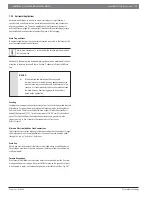
Filter size
The
E
coer
96
% AFUE Gas Furnace
M
GH96 series does not include a
fi
lter
from
the
manufacturer. The
fi
lter
and
fi
l
er rack must be
fi
eld
supplied
and
fi
eld
installed. A
high velocity
fi
lter
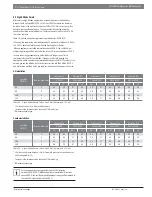
is recommended, see recommended
fi
lter
size and
type in Table 2. One of the most common causes of furnace malfunctions is a
blocked or dirty
fi
lter. The
fi
lter
must
be
inspected
monthly
for
dirt
accumulation
and
replaced if necessary.
Filter type
Air velocity through disposable
fi
lters
may not exceed 300 feet per minute (FPM).
All velocities over this require the use of high velocity
fi
lt
ers. If a normal speed
disposable
fi
lter
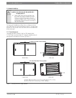
is used and air speed exceeds 300 feet per minute (FPM), two
side returns or one side return and the bottom return may be needed. For air
fl
ow,
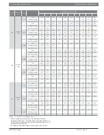
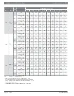
refer to Tables 3 & 4.
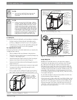
NOTICE:
If disposable
fi
lters are used, air passage through
fi
lters
should be increased to twice the size of original air
opening by using a transition duct or using two
fi
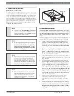
lters in V
shape (see Fig. 19) in normal duct size.
Figure 19
Furnace cabinet width
Filter size
Filter type
Side return
Bottom return
17-1/2
16X25
16X25
High Velocity (600 FPM)
21
16X25
20X25
High Velocity (600 FPM)
24.5
16X25
24X25
High Velocity (600 FPM)
Table 2
Manufacturer recommended high velocity
fi
lter sizes - Inch
Side return
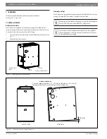
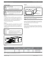
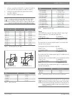
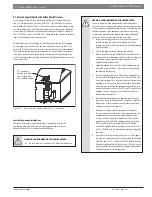
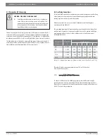
Locate the 4 knockout locations. These indicate the size of the cut-out to be made
in the furnace side panel. Refer to Fig 20, "Side Return Knockout Markings".
Figure 20
Front of
Furnace
Cut out for
side return
Side return knockout markings
Dimensions of return air "cut out" must match those shown in Figure 1.
DO NOT cut outside of the "knockout" markings.
Install the side
fi
lter rack (
fi
eld supplied) following the instructions provided with
that accessory. If a
fi
lter(s) is provided at another location in the return air system,
the duct work may be directly attached to the furnace side panel.
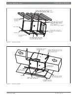
Bottom Return
fi
lters
Filter(s) may be located in the duct system outside the furnace using an external
duct
fi
lter box attached to the furnace plenum or at the end of the duct in a return
fi
lter grille(s). The use of straps and/or supports is required to support the weight
of the external
fi
lter box.

