36
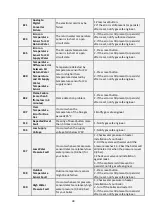
11.3.7- Annual Maintanence Reminder
:
This mode reminds user that “annual
maintanence time is very soon”. When this mode is active, only "ASE" is displayed on
screen and boiler continues to meet heating requests. Electrical connection of boiler
must be always connected to mains, otherwise function will not work properly. When
you see "ASE" on screen, please check your boiler start up date and contact with gas
safe engineer if annual maintanence period is arrived. If maintance of the boiler is
done
before “ASE” appears on screen, you can skip it by pressing “R” button.
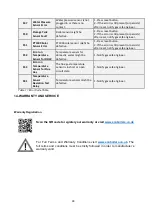
11.3.8- Anti-Frost Mode:
During the winter season, when the installation water temperature falls below
6 ° C, the anti-freeze function is activated and the boiler continues to operate until the water output of
installation rises to 15 ° C. In order for anti-freeze function to be activated, the following conditions must be
checked and ensured by the customer.
The power supply of the boiler must be switched on.
The gas valve and radiator valves must be open.
Water pressure of system should be at appropriate level.
The anti-freeze function helps protect your boiler, it does not protect your installation.
If the boiler will not be operated for a while in places where there is risk of freezing, then it is necessary
to drain the water or to use an anti-freeze agent
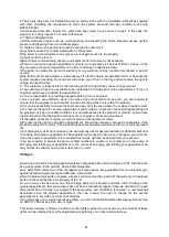
12-GAS CONVERSION
Gas conversion operation from natural gas to LPG must be performed by gas
safe engineer. If the user requests gas transformation after purchase of the
boiler, it is subject to a fee
.
For the gas conversion process, a conversion kit is required.The conversion kit includes
1 gas orifice, 1 gasket and 1 gas conversion label. Procedure for gas conversion is;
Installation of parts in the conversion kit
Gas adjustment
Parameter change (P01: 0 for natural gas, P01:1 for LPG)
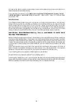
GAS SETTING CHART
Capacity
Gas
Type
Gas
Orifice
Diameter
Orifice
Diameter
Code
P01
Parameter
Max. Fan
Speed
(rpm)
Min. Fan
Speed
(rpm)
Front Cover Closed
CO2
(Max/Min) (%)
24 kW
NG
7.65±0.05 7006990320
0
6250
1850
9.5±0.2 / 8.9±0.2
24 kW
LPG
6.5±0.05 7006990685
1
6100
1850
10.6±0.2 / 9.9±0.2
30 kW
NG
7.9±0.05 7006990688
0
6900
2100
9.5±0.2 / 8.9±0.2
30 kW
LPG
7.1±0.05 7006990691
1
6850
2100
10.6±0.2 / 9.9±0.2
35 kW
NG
8.1±0.05 7006990690
0
7600
2300
9.5±0.2 / 8.9±0.2
35 kW
LPG
7,1±0.05 7006990694
1
7600
2300
10.6±0.2 / 9.9±0.2
Table 10.Gas Setting Table

