Chengdu Ebyte Electronic Technology Co,;Ltd
E30-433T20S user manual
Copyright ©2012–2019
,
Chengdu Ebyte Electronic Technology Co,;Ltd
15
after complete the process.
6
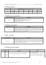
IO drive mode (default 1)
This bit is used to the module internal
pull-up resistor. It also increases the level’s
adaptability in case of open drain. But in
some cases, it may need external pull-up
resistor.
1
TXD and AUX push-pull outputs, RXD pull-up inputs
0
TXD
、
AUX open-collector outputs, RXD open-collector
inputs
5
4
3
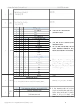
wireless wake-up time
The transmit & receive module work in
mode 0, whose delay time is invalid & can be
arbitrary value.
The transmitter works in mode 1 can transmit
the preamble code of the corresponding time
continuously.
When the receiver works in mode 2, the time
means the monitor interval time (wireless
wake-up). Only the data from transmitter that
works in mode 1 can be received.
0
0
0
250ms (default)
0
0
1
500ms
0
1
0
750ms
0
1
1
1000ms
1
0
0
1250ms
1
0
1
1500ms
1
1
0
1750ms
1
1
1
2000ms
2
FEC switch
After turn off FEC, the actual data
transmission
rate
increases
while
anti-interference ability decreases. Also the
transmission distance is relatively short.
Both communication parties must keep on
the same pages about turn-on or turn-off
FEC.
0
Turn off FEC
1
Turn on FEC (default)
1
0
Transmission power (approximation)
The external power must make sure the ability
of current output more than 400mA and ensure the
power supply ripple within 100mV.
Low power transmission is not recommended
due to its low power supply efficiency.
1
0
Transmission power (approximation)
0
0
20dBm(default)
0
0
17dBm
0
1
14dBm
1
0
10dBm
For example: The meaning of No.3 "SPED" byte:
The binary bit of the byte
7
6
5
4
3
2
1
0
Configures by user
0
0
0
1
1
0
1
0
Meaning
UART parity bit 8N1
UART baud rate is 9600
Air data rate is 2.4k
Corresponding hexadecimal
1
A

