the engineer’s choice
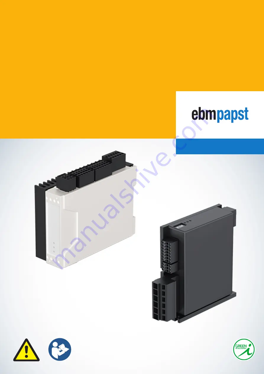
Control electronics
VTD-60.XX-K5SB
Translation of the original operating instructions (EN)
VTD-60.13-K5SB
VTD-60.35-K5SB
Страница 1: ...the engineer s choice Control electronics VTD 60 XX K5SB Translation of the original operating instructions EN VTD 60 13 K5SB VTD 60 35 K5SB...
Страница 2: ...tions 7 2 6 Safety of persons 7 2 7 Electric electromagnetic safety 7 2 8 Intended use 8 2 9 Improper use 8 2 10 Conversions and modifications 9 2 11 Transport and storage 9 2 12 Behavior in the event...
Страница 3: ...ng control electronics to electricity source 25 5 5 Schematic overview 27 5 6 Order of electrical hookup for commissioning 27 5 7 Wiring examples 28 6 Operation 33 6 1 Switching on the control electro...
Страница 4: ...uctions The operating instructions must be available to the user at all times to ensure the device is used safely They must be kept at an easily accessible location at the place of installation where...
Страница 5: ...dicates a list introduced by a heading Underlined blue text indicates a cross reference which can be clicked on in the PDF document Upon doing so the screen will jump to the relevant section of the do...
Страница 6: ...again Do not modify or convert the control electronics or fit any attachments to them without approval from ebm papst Commissioning may only take place following full verification of compliance with a...
Страница 7: ...ctricians are allowed to install the control electronics carry out the trial run and perform work on the electrical system Only authorized specialist personnel are allowed to transport unpack operate...
Страница 8: ...on page 16 Only using the control electronics in stationary systems Starting up the control electronics only after installation in the customer equipment Operating the control electronics with all pr...
Страница 9: ...iginal packaging only Store the control electronics so that they are protected from environmental influences and dirt until final installation We recommend storing the control electronics for no longe...
Страница 10: ...overtemperature monitoring The status of the control electronics is indicated by three LEDs 3 2 Nameplate The nameplate with the relevant control electronics characteristics is applied to the exterio...
Страница 11: ...I O X4 7 n i D 1 t u o D 6 n i D 1 2 3 4 5 6 5 n i D 4 n i D 1 n i A Motor Power X1 6 3 5 2 4 1 D N G c M b M E F a M U p VTD 60 35 K5SB 994 6035 000 9 60 V 35 A IP 20 Made in Germany ebm papst St Geo...
Страница 12: ...3 3 Device view 3 3 1 VTD 60 13 K5SB VTD 60 13 K5SB device view legend Item Designation Item Designation Interface X1 Interface X4 Interface X2 Status LED Interface X3 HEX switch 3 3 2 VTD 60 35 K5SB...
Страница 13: ...p Normal operation Not lit up No power supply Flashing Bootloader mode no firmware LED1 State Yellow Lit up CANopen Pre Operational state PDOs not active Not lit up CANopen Operational state PDOs acti...
Страница 14: ...ork Changing the node address using a HEX switch or software only takes effect after the device has been switched on again Please note that the software node ID see epTools help file Parameter 2000h 2...
Страница 15: ...e transmission speed Index 0 baud rate 1 Mbit s Index 1 baud rate 800 kbit s Index 2 baud rate 500 kbit s Index 3 baud rate 250 kbit s Index 4 baud rate 125 kbit s Index 5 baud rate 100 kbit s Index 6...
Страница 16: ...Logic current draw at 24 V DC mA 60 70 Maximum commutation frequency kHz 2 2 Minimum terminal inductance mH 0 2 0 2 Parametrization interface CANopen CANopen Efficiency in the optimum operating range...
Страница 17: ...urrent controller CURR s 125 Speed controller SVEL s 250 Speed controller VEL s 2000 Position controller POS s 2000 4 6 CAN bus Characteristic Unit VTD 60 13 K5SB VTD 60 35 K5SB Protocol DS301 Device...
Страница 18: ...ngle ended 4 10 Digital inputs Characteristic Unit VTD 60 13 K5SB VTD 60 35 K5SB Number 8 Din 0 to 7 Low level V 0 to 5 High level V 8 to 30 4 11 Digital outputs Characteristic Unit VTD 60 13 K5SB VTD...
Страница 19: ...77146 000 EN Change Release 2020 10 26 Control electronics Control electronics VTD 60 XX K5SB VTD 60 XX K5SB Technical data 4 13 Dimensional drawing VTD 60 13 K5SB 60 4 2 88 9 77 89 33 7 22 5 39 109 5...
Страница 20: ...146 000 EN Change Release 2020 10 26 Control electronics Control electronics VTD 60 XX K5SB VTD 60 XX K5SB Technical data VTD 60 35 K5SB 111 1 132 3 26 100 30 8 92 3 3 9 20 38 4 3 24 5 10 5 4 3 92 3 3...
Страница 21: ...ol electronics immediately and before recommis sioning them check that they are in proper condition WARNING Electromagnetic radiation When integrating the control electronics into the system the inter...
Страница 22: ...or the corresponding ambient conditions Ensure the mechanical protection of the electrical hookup Ensure that the power supply lines are not mixed up Before connecting the motor set the desired parame...
Страница 23: ...60 13 K5SB VTD 60 35 K5SB X1 1 FE Functional earth X1 2 Up Power supply output X1 3 GND Ground output X1 4 Ma Motor phase A X1 5 Mb Motor phase B X1 6 Mc Motor phase C X2 Hall sensors and rotary encod...
Страница 24: ...0 Digital input 0 X3 4 Din 1 Digital input 1 X3 5 Din 2 Digital input 2 X3 6 Din 3 Digital input 3 X3 7 GND Ground electronics X3 8 Ain 0 Analog input 0 negative X3 9 Dout 0 Digital output 0 X3 10 CAN...
Страница 25: ...d to the stripped part of the conductor and not to the insulation Further information can be found at www weidmueller com Connection of the tension spring terminals Weidmueller BLZF 3 5 installed in V...
Страница 26: ...6 0 25 to 6 0 25 to 6 12 Connection of the tension spring terminals Weidmueller B2CF 3 5 interface X2 X3 X4 The drive controllers use connectors with tension spring technology for single fine wire con...
Страница 27: ...ICE Check the pin assignment of your plug see Chapter 5 3 Electrical installation on page 23 Connect the built in connector with the mating connector Ensure that the connector is properly engaged Sche...
Страница 28: ...V from the controller for supplying the motor encoders No external voltage may be applied to this pin If a voltage is applied to the U5V pin X2 7 see Chapter 5 3 1 Interfaces on page 23 on the contro...
Страница 29: ...Change Release 2020 10 26 Control electronics Control electronics VTD 60 XX K5SB VTD 60 XX K5SB Installation 5 7 2 EMC compatible wiring VTD XX 35 K5SB Incremental encoder Hall sensors CAN bus PLC con...
Страница 30: ...motor with encoder differential cables Attention The following cables should be twisted in pairs H1 and H1 H2 and H2 H3 and H3 A and A B and B Inx and Inx M BLDC motor E encoder Fuse slow blow F2 Im...
Страница 31: ...Control electronics Control electronics VTD 60 XX K5SB VTD 60 XX K5SB Installation 5 7 5 Brushed motor 5 7 6 Switch Fuse F1 10 A M motor brushed E encoder Fuse slow blow F2 Im S1 limit switch negativ...
Страница 32: ...o HAB 100177146 000 EN Change Release 2020 10 26 Control electronics Control electronics VTD 60 XX K5SB VTD 60 XX K5SB Installation 5 7 7 Potentiometer 5 7 8 PLC IO control 5 7 9 Controller in SVEL mo...
Страница 33: ...elp file for the software epTools 6 3 Checking functions The LED on the control electronics provides information about the current operating status see Chapter 3 4 Status LED on page 13 6 4 Switching...
Страница 34: ...ookup Danger to life due to electric shock when touching live parts Only allow work to be carried out by a qualified electrician Make sure that the cables are de energized Secure against renewed switc...
Страница 35: ...erved 7 3 2 Disassembly Disassembly of the control electronics must be performed or supervised by qualified personnel with the appropriate technical knowledge The control electronics are to be disasse...
Страница 36: ...de no firmware LED1 State Yellow Not lit up Normal operation Flashing Bootloader mode flashes in the event of in coming message LED2 Error Red Lit up Error Not lit up No error normal operation LED3 Rx...
Страница 37: ...ne 49 9123 945 0 Fax 49 9123 945 145 info4 de ebmpapst com the engineer s choice ebm papst St Georgen GmbH Co KG Hauptverwaltung Head Office Hermann Papst Stra e 1 78112 St Georgen GERMANY Phone 49 77...