background image

3

Section I – Introduction 

A. Reference Material 

Installation dimensions and operating specifications are not
contained in this manual. Refer to installation drawing
501170 for that information.

B. Kits 

A gasket kit is available for this servo valve. It is recom-
mended that new O-Rings and gaskets be used during
overhaul. The part number of the kit is 919529.

x 100 Equals Supply Pressure in psi

3

5

1

3

4

5

1

2

2

Table 1. Model Code Breakdown 

Servo Valve, series, 4-way

x 0.1 Equals Flow Rate in gpm

Model Series

Design No. & Modification

4

Coil Designation - number


x 10

Equals Coil Resistance in Ohms

Figure 1. Exploded View of Servo Valve

30

6

7

5

8

9

36

29

25

24

23

19

18

21

13

12

31

32

33

34

37

1

2

3

4

17

22

16

20

15

14

27

35

28

26

11

10

Pilot
Stage

Содержание Vickers SF4-100-30-002-10

Страница 1: ...Two Stage Flapper Type Servo Valve SF4 140 20 002 10 SF4 100 30 002 10 Overhaul Manual I 3063 S Revised 02 01 74 Vickers Valves...

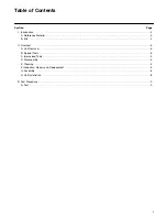
Страница 2: ...ction 3 A Reference Material 3 B Kits 3 II Overhaul 5 A Unit Removal 5 B Special Tools 5 C Improvised Tools 5 D Disassembly 5 E Cleaning 5 F Inspection Repair and Replacement 5 G Assembly 6 H Unit Ins...

Страница 3: ...w O Rings and gaskets be used during overhaul The part number of the kit is 919529 x 100 Equals Supply Pressure in psi 3 5 1 3 4 5 1 2 2 Table 1 Model Code Breakdown Servo Valve series 4 way x 0 1 Equ...

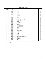
Страница 4: ...16794 7074 323921 O Ring Screw Cover Gasket Screw Nameplate Gasket Screw Clamp Screw Washer Screw and Lock Washer S A Armature Flapper Spring Retaining Ring Coil and Seal O Ring Lock Nut Washer Nozzle...

Страница 5: ...eaning All parts must be thoroughly cleaned and kept clean during inspection and assembly The close tolerance of servo valves makes this requirement more stringent than usual Use a commercial solvent...

Страница 6: ...e valve as follows a Assemble parts 26 22 21 and 20 b Install adjusting screw 25 thru the adapter 26 attach standard nut 24 and washer 23 and turn the nut on until it bottoms against the shoulder of t...

Страница 7: ...nnector with body hole while installing See Figure 4 Tighten the adapter holding screws 10 and washers 11 alternately until the pilot stage is flush against the valve 5 Check spool to see that it does...

Страница 8: ...el Surface finish 125 except where specified H Unit Installation Flush the system through 10 micron full flow filters prior to installing the servo valve A flushing plate can be manufac tured See Figu...

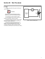
Страница 9: ...g of 190 milliamps is observed on meter c Energize the hydraulic system and adjust for hydrau lic null no movement of hydraulic motor or cylinder with adjustment screw 25 See Figure 1 d Slowly vary th...

Отзывы: