7
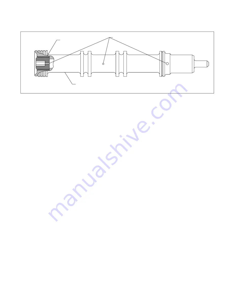
Figure 5. Spool Subassembly
Orifice Plug
See Note:
Holes must be clean
Note: Grip here if orifice plug must be
removed to clean inside of spool.
f. Place a 0.010 shim between the flapper armature (13)
and the nozzle (20) while tightening the two holding screws
and lockwashers (12). See Figure 3.
NOTE
The flapper armature must be square with the
nozzle when the operation is completed and have a
0.010 clearance. A change in the setting of the
adjustment screw (25) may be required during this
procedure to keep the flapper armature square with
the nozzle.
3. Install O-Ring parts (29) thru (27) into valve body
(37).
4. Insert spool subassembly (33) into body (37). The
small end of the spool must extend from the valve
approximately one inch. Assemble the pilot stage (adapter
subassembly (26)) over the spool for alignment purposes.
Guide coil wires thru body hole and align the coil connector
with body hole while installing. See Figure 4. Tighten the
adapter holding screws (10) and washers (11) alternately
until the pilot stage is flush against the valve.
5. Check spool to see that it doesn’t bind in the adapter
(26) then torque the screws to 16-18 lb. in. Recheck for
binding.
6. Assemble the feedback spring (14) to the flapper
armature by twisting the spring over the extrusion until the
spring is tight against the flapper armature. Use a twisting
motion only, lateral force against the flapper armature may
bend it. See Figure 4.
7. Assemble parts (34) and (32) thru (30).
8. Turn adjusting screw (25) until light can just be seen
between the flapper and orifice, point ”A”, Figure 4. This is a
preliminary null adjustment.
9. Assemble clamp (9) and screw (8) over the wire.
Route the wire ends thru the hole to the outside of the valve.
See Figure 4.
NOTE
The name plate, gasket, and screws, parts (7) thru
(5), should not be installed at this time since a final
null adjustment must be made before normal
operation can begin.
10. Install parts (4) thru (1). Torque screws (2) to
16-18 lb. in.


