6
2. Check the 0.060 hole in the nozzle (20).
3. Check frame (22) for cracks or distortion.
4. Check the feedback spring (14) for distortion.
5. Make a continuity check of the coil and seal
subassembly (16). Resistance values should range from 18
to 22 ohms. This test is superficial but a more rigorous test
requires special equipment.
6. Check the adapter (26) and spool mating surfaces.
Insert the spool into the adapter and rotate the spool. The
spool must not bind in any position.
G. Assembly
Replace the gaskets and O-Rings with those supplied in the
gasket kit. Apply a light film of clean system fluid to the parts
prior to installing them. This will make assembly easier and
provide initial lubrication. Special procedures are included in
the following steps:
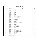
1. Assemble parts (37) thru (35). See Figure 1.
2. Assemble the pilot stage portion of the valve as
follows:
a. Assemble parts (26), (22) , (21) and (20).
b. Install adjusting screw (25) thru the adapter (26),
attach standard nut (24) and washer (23) and turn the nut on
until it bottoms against the shoulder of the adjusting screw.
See Figures 2 and 3.
c. Turn the adjusting screw (25) thru the hole on the
frame (22) far enough to attach the other washer (19) and
lock nut (18).
d. Turn one of the nuts until it contacts the frame,
then tighten the other nut. See Figure 2.
NOTE
After tightening the nuts (18) and (24) against their
respective washers, the adjusting screw (25) should
turn free and have no end play between the screw
and the frame (22).
e. Assemble parts (17) thru (15). See Figure 1.
CAUTION
Be careful when installing flapper armature (13). The
securing screws (12) extend thru the frame (22) and
could break the insultation on the coil. See Figure 3.
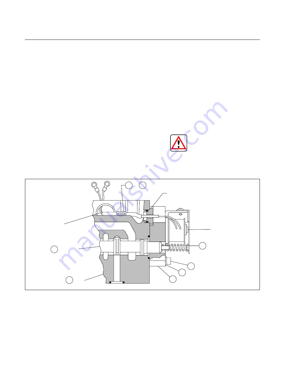
Figure 4. Sectional View
Wires
8
9
14
10
11
26
37
33 Spool S/A
Body
&
Clamp and Screw
Note: Push coil connector out of
body at same time pilot
stage is being removed.
Feedback Spring
Screw
Washer
Adapter S/A
”A”


