9
Section III – Test Procedure
A. Test
1. Utilize your present control system to test the servo
valve as follows:
CAUTION
Check polarity of 0-500 milliammeter with system
polarity prior to installation to prevent meter damage.
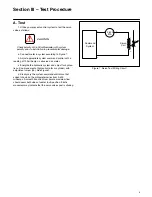
a. Connect meter in system according to Figure 7.
b. Adjust appropriate system command control until a
reading of 190 milliamps is observed on meter.
c. Energize the hydraulic system and adjust for hydrau-
lic null (no movement of hydraulic motor or cylinder) with
adjustment screw (25). See Figure 1.
d. Slowly vary the system command controls so that
current shown on the milliameter varies from 0-400
milliamps. A smooth transition from zero to maximum flow
should occur both sides of center (null) position. Erratic
movement may indicate that the servo valve spool is sticking.
Figure 7. Servo Test Wiring Circuit
Command
System
Servo
Coil
0-500
MA
–
–
+
–
+
+


