background image

EATON  

PVM Piston Pump Service Manual  E-PUIO-II001-E4  December 2017

46

Start–up Procedure

Make sure the reservoir and circuit are clean and free of dirt/

debris prior to filling with hydraulic fluid. Fill the reservoir with 

filtered oil to a level sufficient to prevent vortexing at suc-

tion connection to pump inlet. It is good practice to clean the 

system by flushing and filtering using an external slave pump. 

Before starting the pump, fill with fluid through one of the 

ports. This is particularly important if the pump is above the 

fluid level of the reservoir. When initially starting the pump, 

remove all trapped air from the system. This can be accom-

plished by loosening the pump outlet fittings or connections 

before starting the pump or by using an air bleed valve. All 

inlet connections must be tight to prevent air leaks. Once the 

pump is started it should prime within a few seconds. If the 

pump does not prime, check to make sure that there are no 

restrictions between the reservoir and the inlet to the pump, 

and there are no air leaks in the inlet line and connections. 

Also check to make sure that trapped air can escape at the 

pump outlet. After the pump is primed, tighten the loose 

outlet connections, and then operate for five to ten minutes 

(unloaded) to remove all trapped air from the circuit. If reser-

voir has a sight gauge, make sure the fluid is clear – not milky. 

Add fluid to the reservoir up to the proper fill level. Perform 

functional test on pump according to Eaton test procedure. 

Contact your area sales manager for more information.

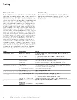
Troubleshooting

The troubleshooting chart below lists common difficulties 

experienced with pumps and hydraulic systems. The chart 

indicates probable causes and remedies for each of the 

troubles listed.

Testing

Trouble 

Probable Cause 

Remedy

Excessive noise in pump 

low oil level in reservoir 

fill reservoir to pepper level with recommended fluid. DO NOT overfill or 


damage may result. 


Air in the system 

1.  Open reservoir cap and operate hydraulic system until purged. 


2.  “Bleed“ hydraulic lines at point downstream of the pump while the 


system is under pressure.


Vacuum condition 

Check inlet (suction) lines and fittings for leaks. 


Oil tool thick 

Be certain correct type of oil is for refilling or adding to the system. 


Cold weather 

Run hydraulic system until unite is warm to the touch and noise disappears.

Hydraulic pump over heating 

Internal leakage 

If established that excessive internal leakage exist within the pump, return to 


maintenance shop for evaluation and repair. 


Heat exchanger not functioning 

Locate trouble and repair or replace. 


Fluid level low 

Add oil to proper operating level.

System not developing pressure  Compensator malfunction 

Replace or repair. 


Loss of fluid internally (slippage) 

Return to maintenance shop for evaluation and repair.

Loss of fluid 

Ruptured hydraulic line 

1.  Check all external connections, tubing and hoses. 


2.  Tighten connections, replace ruptured tube or hose. 


Leaking gaskets or seals in the 

Observe mating section of pump for leaks. Replace seals of gaskets in 


system 

possible. Check all system components for leaks.

Miscellaneous 

Broken or mis-adjusted 

Adjust or replace pump control. 


pump control 


Disconnected or broken drive 

Locate and repair. 

 mechanism

Содержание PVM018

Страница 1: ...PVM Piston Pumps Service Manual PVM018 020 PVM045 050 PVM057 063 PVM074 081 PVM098 106 PVM131 141...

Страница 2: ...fication 4 PVM 018 020 9 PVM 045 050 14 PVM 057 063 15 PVM 074 081 19 PVM 098 106 24 PVM 131 141 29 Repair General Information 34 Replacement Parts Required Tools Special Tools Disassembly Inspection...

Страница 3: ...valve plate so that the pistons pass the inlet as they are pulled out and pass the outlet as they are forced back in The displacement of axial piston pumps is determined by the size and number of pis...

Страница 4: ...V PP TP 0001 E July 2011 6 35 32 33 27 25 1 2 3 4 23 23 73 74 72 23 26 29 24 21 30 36 10 9 58 59 60 61 57 62 63 66 37 34 38 41 40 39 22 47 45 46 44 43 42 48 52 53 54 55 56 31 5 6 65 64 49 51 50 8 7 15...

Страница 5: ...1 B O Ring 45 115001 022 1 B Back Up Ring Item Part No Qty Note Description 46 104166 022 1 B O Ring 47 16028 303 1 Pin 48 932921 1 M Chain Link 49 943992 1 Swashplate 50 02 340318 2 D Cradle Bearing...

Страница 6: ...46 4992730 002 07 C O 937447 08 C O 937448 15 B O 937456 4992728 001 17 D O 937088 4992728 002 01 A O 937183 4992730 006 02 A O 937184 4992730 007 03 B C O 937185 04 A B C O 937186 05 C A 937449 49927...

Страница 7: ...40 L E05 944170 Table 6 End Cover Non Thru Drive 23 Model Code Position 8 13 14 25 R 01 A B 937460 R 02 A B 937187 R 03 A B 937461 R 04 A B 937188 R 05 A B 937462 R 03 G H 937463 R 04 G H 937189 R 05...

Страница 8: ...01 SAE J514 tube ports 02 SAE J518 flange ports 03 ISO 6149 1 tube ports 04 ISO 6162 flange ports 15 16 Pump Special Features 00 None single shaft seal AA Adjustable maximum displacement stop and sin...

Страница 9: ...Identification of Parts Model PVM045 Model PVM050 23 30 36 22 21 24 29 23 4 3 1 2 27 33 32 35 26 23 72 69 71 74 70 73 37 34 38 41 40 39 10 58 60 59 61 57 62 63 66 9 31 47 45 46 44 43 42 48 52 53 54 55...

Страница 10: ...g 45 114998 027 1 B Back Up Ring Item Part No Qty Note Description 46 104166 027 1 B O Ring 47 95902 050 1 Pin 48 932921 1 M Chain Link 49 932918 1 Swashplate 50 937055 2 D Cradle Bearing 51 114995 01...

Страница 11: ...able 1 Pressure Compensator 1 SAE Port Metric Port BSPP Port Model Code Position 9 10 11 26 05 C O 934380 22971 06 C O 934381 58303 96098 100 07 C O 934382 08 C O 932927 05 C A B G H 934391 22971 06 C...

Страница 12: ...03 A B 934359 115050 022 R 04 A B 934269 115050 022 R 05 A B 934363 4992947 002 R 03 G H 934365 115050 022 R 04 G H 934364 115050 022 R 05 G H 934366 4992947 002 R 01 C D 934301 115046 006 934294 R 02...

Страница 13: ...Pump Special Features 00 None single shaft seal AA Adjustable maximum displacement stop and single shaft seal standard AB Double shaft seal two way AD Adjustable maximum displacement stop and double s...

Страница 14: ...36 37 34 38 41 40 39 57 61 60 59 58 31 9 10 30 22 22 21 28 29 47 25 26 27 3 23 1 73 23 70 69 71 72 2 24 5 6 68 66 67 64 65 49 51 50 8 15 16 14 11 29 12 18 15 17 19 56 55 54 53 52 45 46 44 43 42 48 Pa...

Страница 15: ...p Ring Item Part No Qty Note Description 46 104166 126 1 B O Ring 47 16028 303 1 Pin 48 934493 1 M Chain Link 49 934086 1 Swashplate 50 943984 2 D Cradle Bearing 51 114995 010 2 D Screw Socket Flat He...

Страница 16: ...7 C A to M 937383 08 C A to M 937384 09 E G A to M 937380 11 E G A to M 937051 17 E H A to M 939386 18 E H A to M 937385 Table 2 Shaft and Key 5 6 Model Code Position 11 13 14 15 16 C 01 02 00 AA AC 9...

Страница 17: ...43809 L 02 A B 937258 576601 L 02 C D 937258 934296 401525 576601 L 02 E F 937258 934298 353264 576601 L 04 A B 937259 576601 L 04 C D 937259 934567 401525 576601 L 04 E F 937259 934569 353264 576601...

Страница 18: ...SAE J518 flange ports 03 ISO 6149 1 tube ports 04 ISO 6162 flange ports 15 16 Pump Special Features 00 None single shaft seal AA Adjustable maximum displacement stop and single shaft seal standard AB...

Страница 19: ...n Pumps Parts Manual V PP TP 0001 E July 2011 30 71 73 70 69 27 72 23 26 26 24 1 29 32 33 35 28 34 37 36 40 39 41 38 3 47 25 2 21 22 30 10 9 31 58 59 60 61 57 23 23 55 56 54 53 52 43 44 46 45 11 29 14...

Страница 20: ...ng 45 115000 129 1 B Back Up Ring Item Part No Qty Note Description 46 104166 129 1 B O Ring 47 95902 050 1 Pin 48 943252 1 M Chain Link 49 943356 1 Swashplate 50 943378 2 D Cradle Bearing 51 114995 0...

Страница 21: ...3430 18 O 943431 4992727 001 19 O 943432 09 A M 943433 10 A M 943434 11 A M 943435 12 A M 943436 18 A M 943437 4992727 001 19 A M 943438 Table 2 Shaft and Key 5 6 Model Code Position 11 13 14 15 16 E...

Страница 22: ...943809 L 02 A B 943393 576601 L 02 C D 943393 934296 401525 576601 L 02 E F 943393 934298 353264 576601 L 04 A B 943425 576601 L 04 C D 943425 934296 401525 576601 L 04 E F 943425 934569 353264 57660...

Страница 23: ...aft seal AA Adjustable maximum displacement stop and single shaft seal standard AB Double shaft seal two way AD Adjustable maximum displacement stop and double shaft seal 17 Control 0 None A Pressure...

Страница 24: ...n Pumps Parts Manual V PP TP 0001 E July 2011 36 Identification of Parts Model PVM098 Model PVM106 71 73 70 69 27 72 23 26 26 24 1 29 32 33 35 28 34 37 36 40 39 41 38 3 47 25 2 21 22 30 10 9 31 58 59...

Страница 25: ...g 45 115000 129 1 B Back Up Ring Item Part No Qty Note Description 46 104166 129 1 B O Ring 47 95902 050 1 Pin 48 943252 1 M Chain Link 49 943206 1 Swashplate 50 943226 2 D Cradle Bearing 51 114995 01...

Страница 26: ...2 O 943307 18 O 943308 4992727 001 19 O 943309 09 A M 943310 10 A M 943311 11 A M 943312 12 A M 943313 18 A M 943314 4992727 001 19 A M 943315 Table 2 Shaft and Key 5 6 Model Code Position 11 13 14 15...

Страница 27: ...B 943246 576601 L 02 C D 943246 934296 401525 576601 L 02 E F 943246 934298 353264 576601 L 04 A B 943302 576601 L 04 C D 943302 934567 401525 576601 L 04 E F 943302 934569 353264 576601 L 04 G H 943...

Страница 28: ...ft seal AA Adjustable maximum displacement stop and single shaft seal standard AB Double shaft seal two way AD Adjustable maximum displacement stop and double shaft seal 17 Control 0 None A Pressure c...

Страница 29: ...1 E July 2011 42 35 28 2 33 36 37 34 32 27 23 24 26 22 21 29 3 30 59 45 46 44 43 42 31 10 9 58 59 60 61 1 73 23 72 69 70 71 26 26 26 26 23 26 57 38 5 6 40 41 39 48 66 67 68 65 64 49 51 50 8 15 16 14 2...

Страница 30: ...B Back Up Ring Item Part No Qty Note Description 46 104166 032 1 B O Ring 47 95902 050 1 Pin 48 934026 1 M Chain Link 49 933089 1 Swashplate 50 933095 2 D Cradle Bearing 51 114995 010 2 D Screw Socket...

Страница 31: ...7 09 E G A F 934469 114516 10 E G A F 934471 140282 11 E G A F 934470 12 E G A F 934295 13 J A F 934472 633260 14 J A F 934321 18 F H A F 934473 928546 19 F H A F 934475 928547 Table 2 Shaft and Key 5...

Страница 32: ...43809 L 02 A B 934505 576601 L 02 C D 934505 934296 401525 576601 L 02 E F 934505 934298 353264 576601 L 04 A B 934506 576601 L 04 C D 934506 934567 401525 576601 L 04 E F 934506 934569 353264 576601...

Страница 33: ...15 16 Pump Special Features 00 None single shaft seal AA Adjustable maximum displacement stop and single shaft seal standard AB Double shaft seal two way AD Adjustable maximum displacement stop and d...

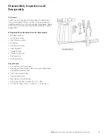
Страница 34: ...Required Tools Ball peen hammer Plastic tip hammer Hex Allen wrenches Wrenches Flat tip screw driver Lock ring pliers Torque Wrench Rubber tip hammer Petroleum jelly Cleaning solvent Read this assembl...

Страница 35: ...ttempted without proper tools B Required Tools Standard Tools for Disassembly Ball peen hammer Plastic tip hammer Hex Allen wrenches Wrenches Flat tip screw driver Lock ring pliers Torque Wrench Rubbe...

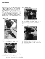
Страница 36: ...ess However it must be filtered to remove water and other con tamination 1 Remove Control Note Remove and discard three O rings 2 Remove Maximum Displacement Stop Screw Note Remove lock nut and turn t...

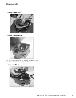
Страница 37: ...irst Then remove rotating group with swash plate and control piston sub assembly The complete rotating group consists of items 57 through 65 WARNING DO NOT remove retaining ring from cylinder block be...

Страница 38: ...O NOT remove retaining ring from cylinder block because spring is under high compression Bodily harm may result if the retaining ring is removed without adequate caution In most cases the parts inside...

Страница 39: ...PUIO II001 E4 December 2017 39 13 Remove Shaft Bearing 14 Remove Saddle Bearings NOTE Tap directly on the hex driver with a ball peen hammer before remov ing retaining screws The screws should be disc...

Страница 40: ...linder block bores NO BINDING CAN BE TOLERATED If binding occurs clean the cylinder block and pistons Lubricate the cylinder block bores with clean fluid and try again Even minor contamination of the...

Страница 41: ...d excessive end play Replace if defective If the bearing needs to be replaced the bearing race also requires replace ment 3 Inspect housing mounting flange for nicks and burrs Re move minor nicks and...

Страница 42: ...O rings and backup rings The minor OD seals are installed in reverse order to the major OD seals 3 The Control Sleeve and Piston Sub assembly to the Swash Plate For fixed hold down assemblies 57cc to...

Страница 43: ...ssembly 5 Install Shaft Seal and Shaft Bearing 6 Installation of Saddle Bearings Note Torque retaining screws to specified torque The bearings should be fully seated in the flange journals 7 Install B...

Страница 44: ...Flange 11 Assemble Screws Attaching Housing to Mounting Flange 12 Install the Shaft Bearing Spacer and Trail Bearing Cone 13 Install Valve Plate on End Cover Note Lightly coat the back plate side of...

Страница 45: ...Pump Service Manual E PUIO II001 E4 December 2017 45 15 Install Alignment Pin in Control Sleeve and End Cover 16 Install End Cover Screws Note Torque the control cap to the specified torque 17 Install...

Страница 46: ...sales manager for more information Troubleshooting The troubleshooting chart below lists common difficulties experienced with pumps and hydraulic systems The chart indicates probable causes and remed...

Страница 47: ...stners Pump Size Item 22 84 Item 26 Item 27 Item 32 PVM 18 20 60 64 N m 60 64 N m 59 73 N m 185 205 N m PVM 45 50 75 83 N m 23 26 N m 103 127 N m 210 230 N m Torque Rating for Plugs and Fastners Item...

Страница 48: ...N 55344 USA Tel 952 937 9800 Fax 952 294 7722 www eaton com hydraulics Eaton Hydraulics Group Europe Route de la Longeraie 7 1110 Morges Switzerland Tel 41 0 21 811 4600 Fax 41 0 21 811 4601 Eaton Hyd...

Отзывы: