EATON
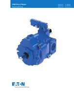
PVM Piston Pump Service Manual E-PUIO-II001-E4 December 2017
3
Basic Pump
Figure 1 shows the basic construction of the PVM series
piston pump. Major parts include the 1. Shaft 2. Housing,
3. Swash plate,4. Rotating group, 5. Valve plate, 6. Control
sleeve, 7. Control rod, 8. End Cover, 9. Control 10. Flange
Figure 1
Pump Operation
In axial piston pumps, the pistons reciprocate parallel to the
axis of rotation of the cylinder barrel. The simplest type of
axial piston pump is the swash plate in-line design. The cyl-
inder barrel in this pump is turned by the drive shaft. Pistons
fitted to bores in the cylinder barrel are connected through
piston shoes and a shoe plate, so that the shoes bear against
an angled swash plate.
As the barrel turns, the piston shoes follow the swash plate,
causing the pistons to reciprocate. The ports are arranged in
the valve plate so that the pistons pass the inlet as they are
pulled out and pass the outlet as they are forced back in. The
displacement of axial piston pumps is determined by the size
and number of pistons, as well as the stroke length which
is determined by the angle of the swash plate. In variable
displacement Models of the in-line pump, the swash plate is
installed in a saddle Bearing. “Pivoting” the swash plate in
saddle bearings changes the swash plate angle to increase or
decrease the piston stroke.
Pump Controls Types
Three common pump control types are available. One type is
the standard “A” compensator control that limits pump outlet
pressure to a desired level. The other type is the “B+C”
pressure limited/load sensing control. Now available is the
“IC” (Industrial Control) which can be used as a load sensing
compensator, remote compensator control and electrohydrau-
lic control. These limit pump outlet pressure and also regulate
pump displacement to match load requirements. A cold start
valve option is also available.
Pump Description

