background image

EATON

Powerware

®

5125 (9910-E65) UPS Installation Guide for IBM

®

Applications

S

164201698 Rev 1

41

Chapter 4

Service and Support

In the United States and Canada, call

1-800-IBMSERV

(1-800-426-7378). In

Europe, the Middle East, and Africa (EMEA); Latin America; or
Asia-Pacific, call the

IBM office

that services your account. Please have

your serial, model, and part number ready when you call (see Figure 29).

For additional information, see the appropriate user’s guide for the UPS
or Extended Battery Module (EBM).

(S/N Bar Code 39)

Part Number

S991010R4AAA

(Data: P42R8077)

(IBM Part Number Bar Code 39)

Front Panel Label

Rear Panel Label

Model Number

Serial Number

IBM/UPS
Type-Model/Feature: 9910-E65
(P) IBM P/N: 42R8077

(S) Serial Number: 9910-10R4AAA

(2P) EC: H89696

(Serial Number Bar Code 39)

(Data: S991010R4AAA)

(Data: 2PH89696)

(EC Number Bar Code 39)

Assembled in Mexico

Date of MFG: YYYYMMDD

Serial Number

Figure 29. Example of IBM Serial Number Labels

Comments

We welcome your comments about this manual. Please send your
questions or suggestions for improvements to
[email protected].

Содержание Powerware 5125

Страница 1: ...Powerware 5125 9910 E65 UPS Installation Guide for IBM Applications ...

Страница 2: ... X Slot and LanSafe are registered trademarks and ConnectUPS is a trademark of Eaton Corporation or its subsidiaries and affiliates Microsoft and Windows are registered trademarks of Microsoft Corporation Linux is a registered trademark of Linus Torvalds Burndy is a registered trademark of Framatone Connectors International ECopyright 2007 Eaton Corporation Raleigh NC USA All rights reserved No pa...

Страница 3: ...ional information such as important operating and maintenance instructions This symbol indicates that you should not discard the UPS or the UPS batteries in the trash This product contains sealed lead acid batteries and must be disposed of properly For more information contact your local recycling reuse or hazardous waste center This symbol indicates that you should not discard waste electrical or...

Страница 4: ...This page intentionally left blank ...

Страница 5: ...wer off Installation 17 Power Connections and Startup 19 Load Segments 25 2 Operation 27 Turning the UPS On 27 Starting the UPS on Battery 27 Turning the UPS Off 27 Initiating the Self Test 28 Operating Modes 28 Normal Mode 29 Battery Mode 29 Bypass Mode 30 Standby Mode 30 Configuration Mode 30 3 Communication Options 35 i5 iSeries or AS 400 and Serial Server Interface Overview 35 Serial TTY Inter...

Страница 6: ...TABLE OF CONTENTS EATON Powerware 5125 9910 E65 UPS Installation Guide for IBM Applications S 164201698 Rev 1 ii This page intentionally left blank ...

Страница 7: ...42R8078 103004715 3992 E65 Accessory Kit 2 39J4828 103004696 3991 Battery Trays If the UPS is factory installed in an IBM rack these items are pre assembled Table 2 E65 Application Matrix IBM MN IBM FC IBM PN Eaton PN Description Quantity for p5 pSeries Rack Worldwide Quantity for i5 iSeriest Rack Worldwide 29391 42R4332 103004741 5591 Relay Serial Card and Cable Kit DB 9 1 8m 6 ft DB 25 9 1m 30 f...

Страница 8: ... pSeries Table 4 E65 Accessory Kit 42R8078 Quantity Eaton PN Description 1 164201541 Powerware 5125 Rack Mount UPS 5000 6000 VA User s Guide 1 164201698 Powerware 5125 9910 E65 Installation Guide for IBM Applications 4 152601942 001 IEC 320 C13 to C14 10A Equipment Power Cords 2m 6 6 ft 1 152601971 001 IEC 320 C19 to C20 16A Equipment Power Cord 4 5m 14 8 ft 1 103004870 Software Suite CD 1 1578090...

Страница 9: ...M Accessory Kit 42R8076 Quantity Eaton PN Description 1 164201518 Powerware 240V Extended Battery Module EBM 240 User s Guide 1 103002843 3992 Rail Hardware Kit metric S 8 M5 12 Pan Head Screws S 8 M5 10 Flat Head Screws S 4 M5 16 Hex Head Screws S 4 M5 Clip Nuts S 2 Square Hole Adapter Plates 2 157605902 003 Joining Brackets 4 180500153 306 Joining Bracket Screws M4 10 mm Setup and Installation T...

Страница 10: ...ing rails are required for each individual cabinet and are located in the UPS and EBM cartons All hardware is supplied NOTE If placing the E65 in a rack with existing equipment the rack must be reconfigured to install the heaviest item in the bottom of the rack The UPS weighs 73 kg 161 lb and the EBM weighs 77 1 kg 170 lb Each rail kit requires one 1 of each item in the following list S Left adjus...

Страница 11: ...emblies and adjust the rail size for the depth of your rack see Figure 1 Rear Front Rail Assembly Assembly Wing Nuts Figure 1 Adjusting the Rail Depth 2 Select the proper holes in the rail for positioning the UPS and any optional cabinets in the rack Place the first rail at the bottom using positions 1 and 6 for the front pan head screws If you are installing additional rails place the next rail 4...

Страница 12: ... Position 6 Position 10 Position 15 First Rail Second Rail Figure 2 Front Rack Screw Positions 3 Secure the rail to the front of the rack with two pan head screws and one adapter plate Insert the screws through positions 3 and 4 of the rail see Figure 3 NOTE Do not tighten the screws until the UPS or EBM is installed ...

Страница 13: ...ng the Front of the Rail 4 Using two clip nuts and two hex head screws attach the rail to the rear of the rack see Figure 4 and Figure 5 The bottom rail uses positions 2 and 4 for the rear hex head screws If you are installing additional rails place the next rail 7 holes above the last installed screw Position 2 Position 4 Position 11 Position 13 First Rail Second Rail Figure 4 Rear Rack Screw Pos...

Страница 14: ...rware 5125 9910 E65 UPS Installation Guide for IBM Applications S 164201698 Rev 1 8 Clip Nuts Figure 5 Securing the Rear of the Rail 5 Repeat Steps 3 and 4 for each rail 6 Tighten the assembly wing nuts on all rail assemblies ...

Страница 15: ...at stable surface with the front of the UPS facing toward you 8 Align the mounting brackets with the screw holes on the side of the UPS and secure with the supplied 6 32 3 8 flat head screws see Figure 6 9 If installing an optional EBM repeat Steps 7 and 8 for each cabinet Mounting Bracket Figure 6 Installing the Mounting Brackets ...

Страница 16: ...re heavy A minimum of two people are required to lift the cabinets into the rack 10 Slide the UPS and any optional EBMs into the rack 11 Secure the front of the UPS to the rack using two pan head screws in the top and bottom positions of each mounting bracket see Figure 7 Repeat for each cabinet Optional EBM UPS Pan Head Screws Figure 7 Securing the Mounting Brackets ...

Страница 17: ...osen the wing nuts on the rear hold down bracket and slide the bracket into the slot on the UPS rear panel Verify that the rear hold down bracket is fully seated and then tighten the wing nuts Wing Nuts on Rear Hold Down Bracket attached to rail Rear Hold Down Bracket for UPS Figure 8 Securing the Back of the UPS ...

Страница 18: ...acket into the slots on the EBM rear panel Verify that the rear hold down bracket is fully seated and then tighten the wing nut Wing Nut on Rear Hold Down Bracket attached to rail Rear Hold Down Bracket for EBM Figure 9 Securing the Back of the EBM 14 Tighten the pan head screws that secure both rails to the front of the rack see Step 3 on page 6 15 Continue to the following section Installing the...

Страница 19: ... chassis 1 Locate the cartons labeled Battery Tray IBM PN 39J4828 2 Verify that the battery circuit breaker on the UPS rear panel is in the OFF position see Figure 13 on page 15 3 Unscrew and set aside the battery retaining bracket see Figure 10 Battery Retaining Bracket Figure 10 Removing the Battery Retaining Bracket 4 Slide the battery trays into the chassis see Figure 11 Figure 11 Installing t...

Страница 20: ...over 7 If you are installing an optional EBM continue to the following section EBM Installation otherwise continue to UPS Installation on page 16 EBM Installation CAUTION A small amount of arcing may occur when connecting an EBM to the UPS This is normal and will not harm personnel Insert the EBM cable into the UPS battery connector quickly and firmly To install the optional EBM s 1 Verify that al...

Страница 21: ... first EBM Repeat for each additional EBM Up to four EBMs may be connected to the UPS 4 Continue to the following section UPS Installation NOTE After UPS installation ensure maximum battery runtime by configuring the UPS for the correct number of EBMs see Configuration Mode on page 30 UPS Battery Connector EBM Cable EBM Battery Connectors Battery Circuit Breakers Battery Circuit Breaker Figure 13 ...

Страница 22: ...5 accessory kit 2 If your rack has conductors for grounding or bonding of ungrounded metal parts connect the ground cable not included to the ground bonding screw Load Segment Circuit Breakers USB Port Battery Connector Communication Port Battery Circuit Breaker IEC 320 C19 Receptacles L6 30 Receptacle IEC 320 C13 Receptacles Power Cord 0 9m 3 ft with L6 30 Plug X Slot Communication Bay Ground Bon...

Страница 23: ...de when restarted until the On button is pressed WARNING The REPO circuit is an IEC 60950 safety extra low voltage SELV circuit This circuit must be separated from any hazardous voltage circuits by reinforced insulation CAUTION To ensure the UPS stops supplying power to the load during any mode of operation the input power must be disconnected from the UPS when the emergency power off function is ...

Страница 24: ...5 mm2 0 5 mm2 18 20 AWG NOTE A separate contact must simultaneously cause UPS input AC power to be removed 4 Reconnect the REPO connector to the REPO port Pin 1 Pin 2 Figure 15 REPO Connector 5 Verify that the externally connected REPO switch is not activated to enable power to the UPS output receptacles 6 Plug in the UPS and start the UPS by pressing the On button for approximately three seconds ...

Страница 25: ...to UPS power cord 3 PDU to utility mains power cord UPS PDU Mains 1 2 Figure 16 Connecting One PDU Non Redundant to UPS Mains 1 2 3 TVSS Protected or Second UPS UPS PDU Mains PDU Figure 17 Connecting Two PDUs Dual Redundant to UPS 1 If you are installing a UPS and non redundant power to the device s is desired plug the PDU power cord into the UPS output receptacle see Figure 16 using the supplied ...

Страница 26: ... the UPS capacity 3 Verify that all load segment circuit breakers are in the ON position 4 Remove the breaker tie from all battery circuit breakers 5 Switch all battery circuit breakers to the ON position 6 Plug the UPS power cord into a power outlet The μ indicator flashes indicating the UPS is in Standby mode with the equipment offline 7 Press and hold the On button for approximately three secon...

Страница 27: ...System i E65 Product Literature S Submit your question to Ask the Expert at www powerware com ibm S Submit your question to our FAQ database at www powerware com Iibm and select General Knowledge Frequently Asked Questions S Contact the IBM office or Business Partner servicing your account Table 8 Typical Power Connections Figure 18 Figure 20 Item Description 1 NEMA L6 30R 2 NEMA L6 30P 3 IEC 320 ...

Страница 28: ...3m 14 ft 6656 46 IBM Burndy to IEC 309 P N G 32A 4 3m 14 ft 6657 PDL IBM Burndy to PDL 4 3m 14 ft 6658 KP IBM Burndy to KP 4 3m 14 ft 9 2974 Eaton Burndy to IEC 320 C20 1 8m 6 ft 10 Output power UPS to device cords located in the E65 accessory kit Qty Description 4 IEC 320 C13 to C14 1 8m 6 ft 1 IEC 320 C19 to C20 2 7m 9 ft Other power cords are supported by the PDU Power cords shown are similar i...

Страница 29: ...89 or 7109 Device E65 4500W UPS 1 2 6 Mains Varies 5 5 3 3 3 3 4 4 4 4 10 Figure 18 E65 with Non Redundant Power 7 IBM 6 6 1 2 PDU IBM iSeries or pSeries 7188 9188 5889 or 7109 Device E65 4500W UPS 1 2 6 Mains Varies 5 5 3 3 3 3 4 4 4 4 9 3 PDU IBM iSeries or pSeries 7188 9188 5889 or 7109 Device 5 5 10 10 Figure 19 E65 with Non Redundant Power to Multiple PDUs ...

Страница 30: ...plications S 164201698 Rev 1 24 IBM 6 6 1 2 PDU IBM iSeries or pSeries 7188 9188 5889 or 7109 Device E65 4500W UPS 1 2 6 Mains Varies 5 7 3 3 3 3 4 4 4 4 8 PDU IBM iSeries or pSeries 7188 9188 5889 or 7109 8 Mains Varies 5 IBM 8 5 5 10 10 Figure 20 E65 with Dual Redundant Power ...

Страница 31: ...you turn off other equipment This feature allows you to save battery power See your power management software manual for details refer to the Software Suite CD or www powerware com for the latest information NOTE If power management software is not used the individual load segments cannot be controlled NOTE The circuit breaker for Load Segment 1 does not include the corded receptacle The E65 has t...

Страница 32: ...INSTALLATION EATON Powerware 5125 9910 E65 UPS Installation Guide for IBM Applications S 164201698 Rev 1 26 This page intentionally left blank ...

Страница 33: ...e using this feature the UPS must have been powered by utility power at least once To turn on the UPS without using utility power press and hold the On button for approximately three seconds The UPS supplies power to your equipment and transfers to Battery mode Turning the UPS Off To turn off the UPS 1 Prepare your equipment for shutdown 2 Press and hold the Off button for approximately three seco...

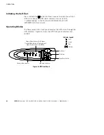
Страница 34: ...in the Powerware 5125 Rack Mount UPS 5000 6000 VA User s Guide Operating Modes The Powerware 5125 s front panel indicates the UPS status through the UPS indicators Figure 22 shows the UPS front panel indicators and controls On Button Off Button Alarm Reset Button Normal Mode Indicator Solid Green Standby Mode Indicator Flashing Green Bypass Mode Indicator Solid Red Red Flashing Unlit Green Indicat...

Страница 35: ... exceed UPS capacity refer to Troubleshooting in the Powerware 5125 Rack Mount UPS 5000 6000 VA User s Guide for more information Battery Mode When the UPS is operating during a power outage the alarm beeps intermittently the indicator illuminates and the μ flashes When the utility power returns the UPS transfers to Normal mode operation while the battery recharges If battery capacity becomes low ...

Страница 36: ...lashes and the load level indicators are off indicating that power is not available to your equipment The battery recharges when necessary Configuration Mode When the UPS is in Configuration mode the front panel indicators represent the configuration options Use the control buttons On button Off button and button to modify the UPS configuration Figure 24 shows the indicators and Table 9 explains t...

Страница 37: ...n NOTE The UPS exits Configuration mode automatically after two minutes of inactivity 4 Press the button to confirm the selection and exit Configuration mode If you do not press the button the UPS defaults to the original settings 3 2 4 On Button Off Button Alarm Reset Button Configuration Mode Indicators Press and hold the On and Alarm Reset buttons simultaneously to enter Configuration mode 1 Pr...

Страница 38: ...e nominal output voltage to 230V p g Flashing 230V is disabled one of the other output voltage options is selected 240V Nominal Output Voltage On Selecting this option changes the nominal output voltage to 240V p g Flashing 240V is disabled one of the other output voltage options is selected Site Wiring Fault Alarm On Alarm sounds when the polarity of the outlet is reversed or the ground connectio...

Страница 39: ...ations S 164201698 Rev 1 33 Explanation Indicator Status Option Configuration Mode Indicators 3 EBMs On Three EBMs are configured Flashing One of the other EBM configurations is selected 4 EBMs On Four EBMs are configured Flashing One of the other EBM configurations is selected ...

Страница 40: ...OPERATION EATON Powerware 5125 9910 E65 UPS Installation Guide for IBM Applications S 164201698 Rev 1 34 This page intentionally left blank ...

Страница 41: ... and or Network WebServer Connection UPS as a node X Follow the installation instructions with the Software Suite CD or the applicable card kit This section shows the communication option overviews For additional information and a current listing of supported operating systems go to www powerware com i5 iSeries or AS 400 and Serial Server Interface Overview To connect the UPS to an i5 iSeries or A...

Страница 42: ... existing X Slot card from the UPS Follow the software installation instructions contained on the Software Suite CD to install the Powerware LanSafe software If you have an i5 connect the cables as shown in Figure 25 Otherwise see Figure 26 to connect the cables AS 400 Interface Cable labeled 152601976 001 UPS Interface Cable labeled 1827 P1 T1 UPS Port IBM i5 Server Serial Interface Cable labeled...

Страница 43: ...ations S 164201698 Rev 1 37 Relay Serial Card Communication Port J14 UPS Port location may vary by model IBM iSeries Server UPS AS 400 Interface Cable labeled 152601976 001 Serial Interface Cable labeled 124102044 001 Serial TTY Server Figure 26 iSeries or AS 400 and Serial Server Interface ...

Страница 44: ...ory kit For p5 installations you also need S An IBM supplied 2 port Asynchronous EIA adapter FC 5723 installed on a p5 server the pSeries does not require an EIA adapter S An IBM supplied maintenance package 5200 05 for AIX 5 2L V5 2 APAR IY66260 or the maintenance package 5300 01 for AIX 5 3L V5 3 APAR IY62267 Follow the software installation instructions contained on the Software Suite CD to ins...

Страница 45: ...mer supplied Ethernet cable S An available Ethernet port on the server Follow the instructions included with the ConnectUPS X Web SNMP Card Kit to install the card and set UPS monitoring functions Installation may include removal of an existing X Slot card from the UPS Follow the software installation instructions contained on the Software Suite CD to install the NetWatch software onto each LPAR C...

Страница 46: ...COMMUNICATION OPTIONS EATON Powerware 5125 9910 E65 UPS Installation Guide for IBM Applications S 164201698 Rev 1 40 This page intentionally left blank ...

Страница 47: ... appropriate user s guide for the UPS or Extended Battery Module EBM S N Bar Code 39 Part Number S991010R4AAA Data P42R8077 IBM Part Number Bar Code 39 Front Panel Label Rear Panel Label Model Number Serial Number IBM UPS Type Model Feature 9910 E65 P IBM P N 42R8077 S Serial Number 9910 10R4AAA 2P EC H89696 Serial Number Bar Code 39 Data S991010R4AAA Data 2PH89696 EC Number Bar Code 39 Assembled ...

Страница 48: ...SERVICE AND SUPPORT EATON Powerware 5125 9910 E65 UPS Installation Guide for IBM Applications S 164201698 Rev 1 42 This page intentionally left blank ...

Страница 49: ...ts are designed to provide reasonable protection against harmful interference when the equipment is operated in a commercial environment This equipment generates uses and can radiate radio frequency energy and if not installed and used in accordance with the instruction manual may cause harmful interference to radio communications Operation of this equipment in a residential area is likely to caus...

Страница 50: ...This page intentionally left blank ...

Страница 51: ......

Страница 52: ... 1642016981 164201698 1 ...

Отзывы: