EATON
Installation & Maintenance Instructions
TM396 – XF-XP-XT LW UL ISS.A
7 |
P a g e
3.0 Installation
In order to ensure proper wiring and system operation of all components, it is recommended that all units
and all associated control equipment be tested at your Factory before field installation is attempted.
3.1
Unboxing & Handling
3.1.1 Unboxing
On receipt of the units ensure that the cartons are undamaged and that the contents are all correct and
complete. After unpacking it is recommended that the packing materials are kept safe, should you need to
return the unit for repair, or maintenance.
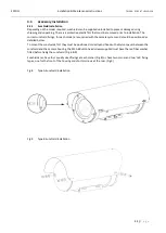
If not already fitted, the protective plastic film should be removed from sunshields prior to fitting.
3.1.2 Handling
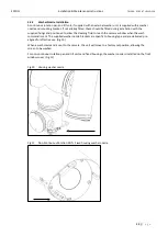
Due to the reinforced steel construction of the camera units, correct handling is of great importance. Lifting
and positioning XP and XT units should always be completed using suitable lifting equipment that is capable
of supporting loads in excess of 65Kg. XP units should be lifted using a strap between the camera housing
and the L-body section. The XT unit should be lifted with 2 straps, equally supporting either side of the T-
body.
The camera housings must not be used for lifting. To avoid damage to the unit DO NOT ATTEMPT to rotate
the camera housings by hand. The units should not be handled using direct contact with ferrous metal
equipment.
(see section 4.1 for details)
3.2
Mounting
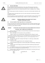
Ensure the desired mounting surface can support four times the combined weight of the complete unit.
Do not stand or place objects “directly under” the installed camera system.
Due care and attention must be taken to ensure enough clearance is allowed, to permit full rotation of the
unit with its associated equipment; and that the moving unit cannot strike or make contact with personnel.
It is strongly advised that the EATON range of mounting brackets are used.
3.2.1 Mounting the XP & XT series
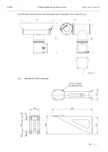
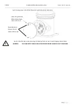
The XP and XT pan/tilt/housing assembly should be mounted horizontally, onto various structures such as
bulkheads, walls or towers. It can also be mounted upside down, in the inverted position.
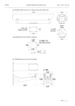
The complete assembly is mounted to the support structure via its base part, which has 11mm clearance
holes for four (4) M10 fixings. (Fig 1)
The type and size of any fixing brackets to be supplied by the user/installer must be suitable for the
installation requirements outlined in this manual.
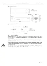
An alternative is to use the BPW6500 Wall mount bracket (Fig 2)


