EATON
Installation & Maintenance Instructions
TM396 – XF-XP-XT LW UL ISS.A
5 |
P a g e
2.0 Description
The Series ‘X’ camera assemblies have been developed to meet the rigorous requirements of Flame proof
and dust-ignition-proof electrical equipment for installation and use in hazardous locations found in the
onshore and offshore, oil & gas and petrochemical installations. The units may also be used in marine and
industrial hazardous environments.
The housing enclosures and all external parts are manufactured entirely of AISI 316L stainless steel for low
maintenance and protection from corrosion.
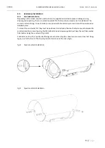
Removable end covers are fixed to the body by five (5) M6 x 12 stainless steel hex cap screws. Cable entry
cover is an M110 x 1.5 screw-fit cover. All fixings conform to the requirements of UL 1203. The
weatherproof seal at the union between enclosures and covers is maintained using ‘O’ ring seals.
The camera housings feature an internal sliding camera mounting rail, which is fitted with an internal
heating element/de-mister, thermostatically controlled to maintain operating temperature, and ensure
clarity of vision through the window. There is an optional integral window wiper mechanism.
The viewing window is made with toughened glass, or in the case of the Thermal Imager and Dual Imager
versions, is made from Infrared transparent material, which is factory fitted with a mechanical window
guard.
THE MECHANICAL THERMAL WINDOW GUARD MUST NOT BE REMOVED.
There are three system types in the ‘Series X’ certified units; these are:
•
XF: Fixed camera housings.
•
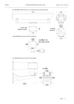
XP: Pan & Tilt units with integral base section for cable connections.
•
XT: Pan & Tilt units with integral base section for cable connection, and a secondary linked housing
for an integrated illuminator.
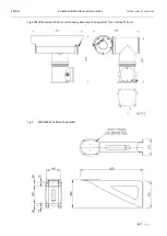
The XF fixed housings comprise a single tube section enclosure with either cable entries in the rear cover or
in the side (model dependent).
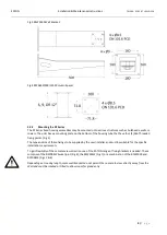
The XP and XT units have a single cable entry into the fixed base section, this prevents any trailing cables.
The Series ‘X’ housings and pan/tilt units have been designed and certified to the UL 1203 Directive, with
the following ratings:
Class I Div 1 Groups B, C, D
Class I Div 1 Groups A, B, C, D
Class II Div 1 Groups E, F, G
Class II Div 1 Groups E, F, G
Class I Zone 1 IIB + Hydrogen
Class I Zone 1 IIC
-60°C to +70°C
-20°C to +70°C
T4 T135°C IP66/67
Note
: T class and ambient temperature, is dependent on the assembly configuration and maximum
internal power dissipation.
*=T class T4A, T5, T6
The project requirements and unit certification label must be checked by the installer before installation, to
confirm that the product supplied is suitable for the intended installation zone and environment.
Manufactured in accordance with
UL 1203 Edn.5, CSA22.2 No30-M1986 Edn1 reaffirmed 2012, CSA C22.2 No25-1966 reaffirmed 2014, CSA
C22.2 No 60065-03 Edn.1, UL60065 Edn.7.
2.1
Versions
There are different camera options available within the range; these include Day/Night cameras with
optional wiper, integral washer or external washer, thermal imager and dual camera day/night and thermal
units.
The range also includes options for HD IP cameras, digital fiber optic convertors and media convertors.
Due to the large number of possible configurations, this manual only covers the standard installation of the
units.


