Installation
i-on30EX/EXD
Page 24
Step 8. Connect the Internal
Communicator (i-on30EXD
only)
The i-on30EXD version of the control unit has an
internal communicator on its main PCB. This is an
auto-dialling modem.
If necessary, a standalone communication device
can be connected through a wiring harness to
interface pins on the main PCB (this is known as a
plug-by communicator, see page 26).
The communicator can be used for:
•
Transmitting alarm signals to alarm receiving
equipment at a central monitoring station
using Scancom Fast Format, Scancom SIA
(Security Industry Association) or Contact ID.
•
Connecting to a PC based at a remote
engineering centre. Using Scantronic
Downloader software, the remote PC can
upload and download system parameters
(including the event log and diagnostics), set
and unset the alarm system, and carry out
other special functions.
Telephone Line
Ideally, the internal communicator should be
connected to an ex-directory line used exclusively
for alarm communications.
Line Monitoring for the Internal Communicator
The control unit provides a line monitoring
function to check that a telephone line connected
directly to the control unit is working, and to
indicate a line failure if it is not. While enabled,
this function continually checks the line voltage to
ensure that the line is connected. If it detects a
failure, the system gives the Line Fault Response
selected in the Installer Menu.
Test Calls
The control unit can be programmed to make test
report calls to an ARC. "Static" test calls can be
programmed to occur at set times or intervals.
"Dynamic" test calls occur 24 hours after the last
call made by the unit. See the
i-on Range
Engineering Guide
for details on how to program
these functions.
Statutory Information
Applications
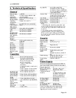
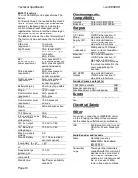
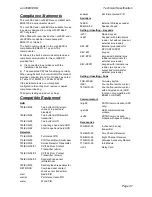
The built-in communicator is suitable for
connection to the following types of networks:
(a) Direct exchange lines (PSTN) supporting
DTMF (tone) dialling.
(b) PABX exchanges (with or without secondary
proceed indication).
Note: The built-in communicator is not suitable for
connection as an extension to a pay-phone or to 1
+ 1 carrier systems.
Approval
The built-in communicator is manufactured to
meet all European Economic Area
telecommunication networks requirements.
However, due to differences between the
individual PSTNs provided in different countries,
the approval does not, of itself, give an
unconditional assurance of successful operation
on every PSTN network termination point.
The built-in communicator has been approved for
the following usage:
(a) Automatic call initialisation.
(b) Operation in absence of indication to proceed.
(c) Automatic dialling.
(d) Modem.
(e) Serial connection.
(f) Multiple repeat attempts.
(g) Line status monitoring.
Usage other than approved usage or failure to
comply with the installation and programming
instructions may invalidate any approval given to
the apparatus if, as a result, the apparatus ceases
to comply with the standards against which
approval was granted. Note the approval label on
the main PCB.
In the event of problems you should contact your
equipment supplier in the first instance.
Ringer Equivalence Number
The Ringer Equivalence Number (REN) of the
built-in communicator is 1. As a guide to the
number of items that can be simultaneously
connected to an exclusive line, the sum of the
REN values should not exceed 4. A standard
telephone (as provided, for example, by BT in the
UK) has a REN value of 1.
Safety Notice
Figure 44 identifies connectors for Safety Extra-
Low Voltage (SELV) and Telecommunications
Network Voltage (TNV) circuits on the control
unit's main PCB. These terms are used in
accordance with the definitions in Safety Standard
EN60 950.
The Installer must ensure that TNV terminals are
connected
only
to other circuits designated as
TNV circuits (for example, the PSTN) and that
SELV terminals are connected
only
to other
circuits designated as SELV circuits. Strict
adherence to the installation instructions will
ensure that the equipment continues to comply
with the safety regulations to which it was
approved.
Содержание i-on30EX
Страница 1: ...i on30EX i on30EXD Security System Installation Guide Issue 6...
Страница 4: ...i on30EX EXD Page iv This page is intentionally blank...
Страница 42: ...i on30EX EXD Page 38 NOTES...
Страница 43: ...i on30EX EXD Page 39 NOTES...


